Method for detecting contact with the wall of a region of interest

a technology for detecting contact and applied in the field of detecting contact with the wall of a region of interest, can solve the problems of inability to fully integrate the detection method, inability to provide a truly robust solution for tool-to-wall contact detection, and limited techniqu

Active Publication Date: 2011-09-29
ST JUDE MEDICAL INT HLDG SARL
View PDF8 Cites 42 Cited by
  • Summary
  • Abstract
  • Description
  • Claims
  • Application Information

AI Technical Summary

Benefits of technology

The present patent describes a way to detect when a tool touches a specific area of the body, such as the heart. This is done by tracking the movement of the tool and creating a profile of the movement of the region of interest. The tool's movement is compared to the movement of the wall of the region of interest, and a correlation value is calculated to determine if the tool is touching the wall. If there is a significant correlation, a contact indicator is activated to alert the user that the tool is touching the wall. The technical effect of this invention is to provide a reliable and efficient method for detecting tool-to-wall contact during medical procedures, which can improve the accuracy and precision of the procedures.

Problems solved by technology

The technical problem addressed in this patent text is the need for a system that can reliably detect when a medical tool makes contact with the wall of a region of interest in the body, to prevent bends or ruptures in the wall and to enable effective treatment or diagnosis. Existing methods such as electrical-based sensing and pressure sensors have limitations, and there is a need for additional methods to determine when contact is made. The patent text also discusses the use of position and orientation sensors in medical imaging and detection systems to determine the location and orientation of medical tools within the body.

Method used


Image

  • Method for detecting contact with the wall of a region of interest
  • Method for detecting contact with the wall of a region of interest
  • Method for detecting contact with the wall of a region of interest

Examples


Embodiment Construction

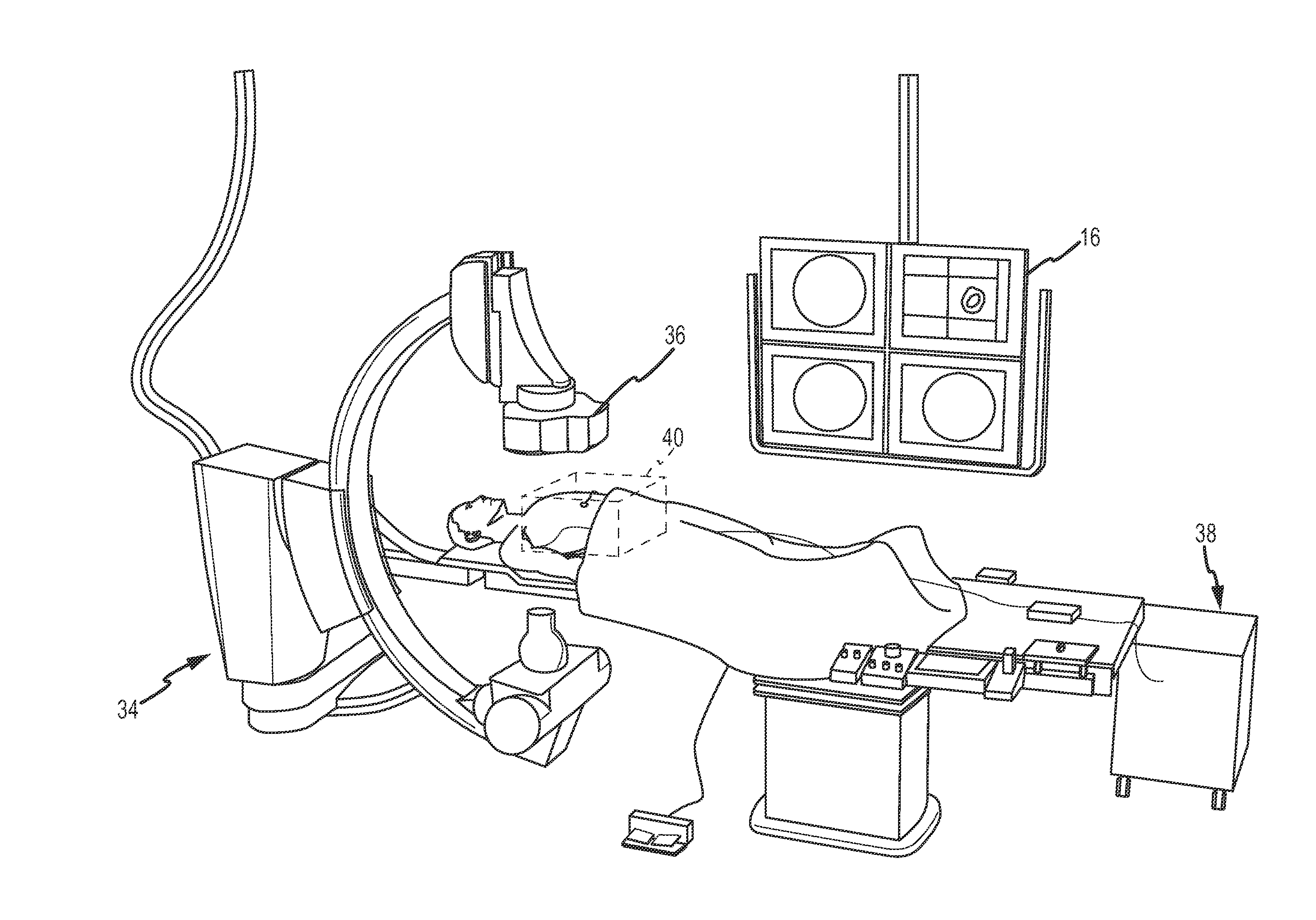
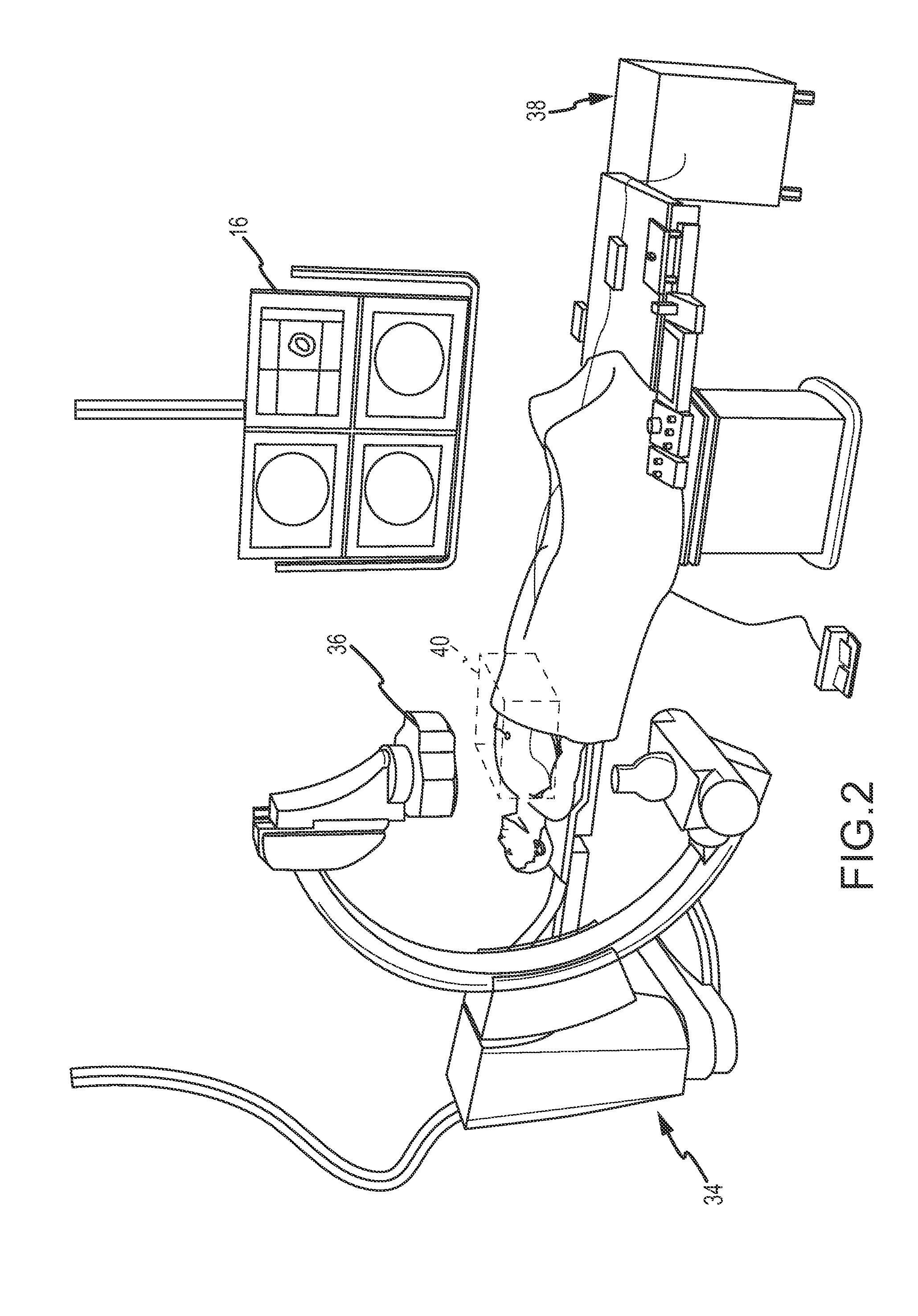
[0020]In general, the instant disclosure describes a system and method for detecting contact of a medical tool with a region of interest, such as for example, a catheter within a heart cavity. For purposes of this description, similar aspects among the various embodiments described herein will be referred to by the same reference number. As will be appreciated, however, the structure of the various aspects may be different among the alternate embodiments.

[0021]The term “position” herein below, refers to the location of a point in space, or a combination thereof. The term “lumen” and / or “organ” herein below, refers to a tubular structure of the human patient or the operated animal, such as an artery, vein, cardiac vessel, heart chamber, brain vessel, part of the urogenital system, nephrotic system, hepatic system, bronchus tree, and the like.

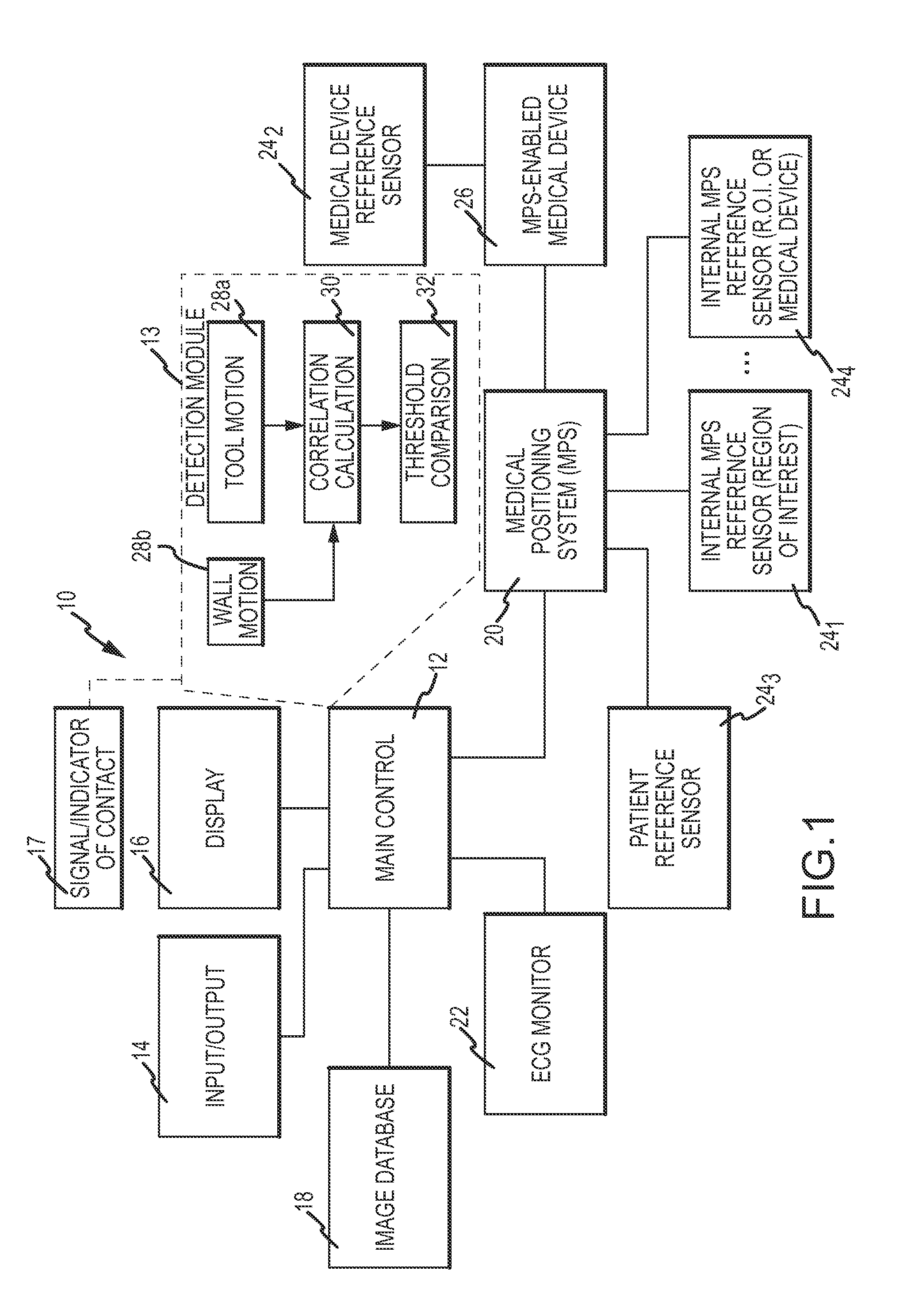
[0022]FIG. 1 is a diagrammatic view of a system 10 in which aspects of the invention may be embodied. It should be understood that while embodim...


PUM


Abstract

A method for detecting when a tool contacts a wall of a region of interest includes the steps of: tracking the motion of the tool and creating a tool motion profile; calculating a correlation value representative of the correlation between the tool motion profile and a wall motion profile indicative of the motion of the wall; and determining when the correlation value exceeds a threshold indicative of contact of the tool with the wall of the region of interest.

Description


Claims


Application Information

Patent Timeline
Owner ST JUDE MEDICAL INT HLDG SARL
Why Eureka
Try Eureka