
Device for displaying the energy variation of an aircraft, corresponding method and system for displaying the energy variation

a technology for aircraft and energy variation, applied in the field of aircraft energy variation display devices, can solve the problems of imposing a heavy workload on the pilot, unable to determine the energy of the aircraft, and unable to view the result of his command in terms of acceleration and gradient, so as to achieve the effect of minimal energy variation

Active Publication Date: 2011-09-29
DASSAULT AVIATION
View PDF25 Cites 15 Cited by
  • Summary
  • Abstract
  • Description
  • Claims
  • Application Information

AI Technical Summary

Benefits of technology

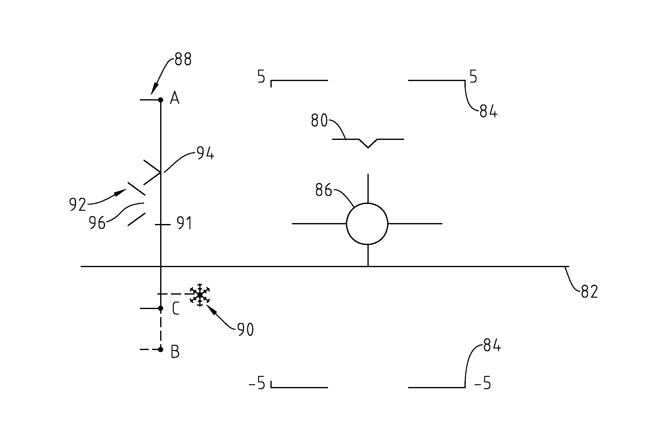
The invention is a display device for aircraft that allows the pilot to directly view the energy variation of the aircraft. The device expresses the energy variation of the aircraft as a size representative of the energy variation range achievable by the aircraft. The device can also show an ordered energy variation and the energy variation range that can be achieved by the aircraft using a braking system or a deicing system. The device can display a graduated scale of the energy variation and show a minimum energy variation that the aircraft can achieve when the braking system is not exerting a drag force on the aircraft. The device can also show a reference indicating the minimum energy variation that can be achieved when the braking system is exerting a drag force on the aircraft. The invention provides a display system for displaying the energy variation of an aircraft and controlling the display on the display device of the current energy variation and the energy variation range that can be achieved by the aircraft.

Problems solved by technology

This viewing alone does not allow the pilot to determine the aircraft's energy, and in particular the variation thereof.
However, when the pilot acts on the gas lever and / or the airbrakes, he can only view the result of his command in terms of acceleration and gradient once the rating is stabilized.
This type of display imposes a heavy workload on the pilot, and can be a source of errors, due in particular to the amount of information that must be analyzed by the pilot and the difficulty of interpreting it in terms of energy.
These display devices, although showing information relative to the energy, do not enable the pilot to know the energy range that can be achieved by the aircraft, which the pilot remains responsible for determining.

Method used


Image

  • Device for displaying the energy variation of an aircraft, corresponding method and system for displaying the energy variation
  • Device for displaying the energy variation of an aircraft, corresponding method and system for displaying the energy variation
  • Device for displaying the energy variation of an aircraft, corresponding method and system for displaying the energy variation

Examples


Embodiment Construction

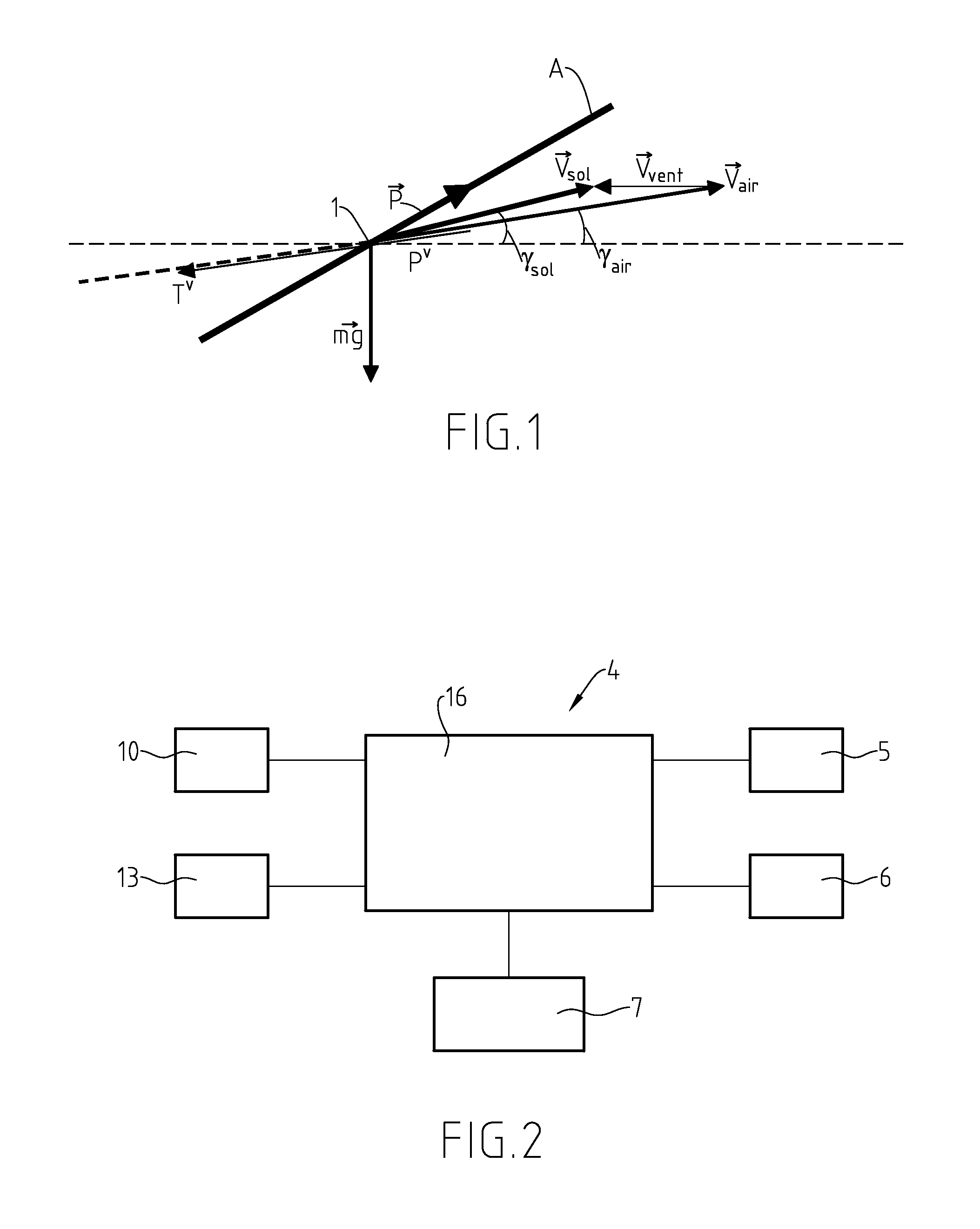
[0058]FIG. 1 shows, diagrammatically, an aircraft 1 in flight to which the inventive method can be applied.

[0059]This aircraft 1, shown by its sole center of gravity, is oriented along an axis A, and moves relative to the air according to a speed vector {right arrow over (Vair)}, which forms, with the horizontal, an angle γair called the air gradient of the aircraft.

[0060]Because the air itself is in motion relative to the ground, according to vector {right arrow over (Vvent)}, the speed of the aircraft 1 relative to the ground is different from its speed relative to the air, and can be expressed by:

{right arrow over (Vsol)}={right arrow over (Vair)}+{right arrow over (Vvent)}.

[0061]This vector {right arrow over (Vsol)} forms, with the horizontal, an angle γsol called the ground gradient of the aircraft.

[0062]The aircraft 1 is provided with a propulsion system, for example a set of engines, exerting a thrust force {right arrow over (P)} on the aircraft, the projection of which on th...


PUM


Abstract

This device for displaying information relative to a flight configuration of the aircraft provided with at least one propulsion system, able to generate a thrust force on said aircraft comprised in a thrust range, said information comprising information relative to an energy variation of the aircraft, is characterized in that the energy variation of the aircraft is expressed by a size representative of this energy variation and homogenous at a gradient of the aircraft, and in that said device is capable of representing a range of energy variations that can be achieved by said aircraft and a current energy variation of said aircraft. Corresponding method and system for displaying an energy variation.

Description

CROSS-REFERENCE TO RELATED APPLICATIONS[0001]This application claims benefit of French patent application number 1001173, filed Mar. 24, 2010, which is herein incorporated by reference.BACKGROUND OF THE INVENTION[0002]1. Field of the Invention[0003]The present invention relates to a device for displaying information relative to a flight configuration of an aircraft provided with at least one propulsion system, able to generate a thrust force on said aircraft comprised in a thrust range, said information comprising information relative to an energy variation of the aircraft, and a corresponding system and method for displaying the energy variation.[0004]2. Description of the Related Art[0005]In the aircrafts according to the state of the art, the pilot manages the aircraft's energy by acting on several controls, and in particular on the gas lever and the airbrake control. The gas lever allows the pilot to control the speed of the engine(s). In response to such a command, the thrust d...

Claims


Application Information

Patent Timeline
Patent Type & Authority Applications(United States)
IPC IPC(8): G06F19/00G01C21/00G01C23/00
CPCG01D7/00G01C23/00G01D2207/10
Inventor BARRAL, JEROMELOPEZ, SALVADORGERARD, ERIC
Owner DASSAULT AVIATION
Learn More