Switch arrangement for an electrical switchgear

Inactive Publication Date: 2012-01-12
EATON INTELLIGENT POWER LIMITED
View PDF47 Cites 5 Cited by
  • Summary
  • Abstract
  • Description
  • Claims
  • Application Information

AI Technical Summary

Benefits of technology

[0013]This arrangement enables an operator to switch between either the first bus or the second bus being connected to a load, in a quick and straightforward manner.

Problems solved by technology

In fixed switchgear the main switching / protective device, for example a circuit breaker, is fastened within the installation by fasteners, for example bolts, and cannot be removed from the installation without using tools to undo the fasteners.

Method used


Image

  • Switch arrangement for an electrical switchgear
  • Switch arrangement for an electrical switchgear
  • Switch arrangement for an electrical switchgear

Examples


Embodiment Construction

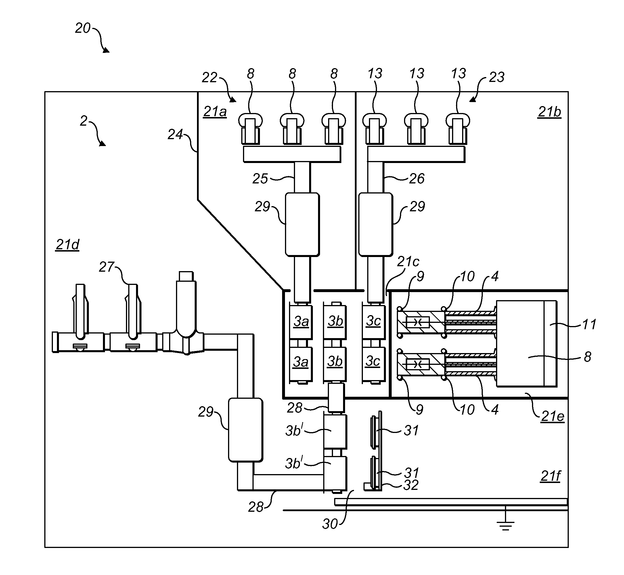
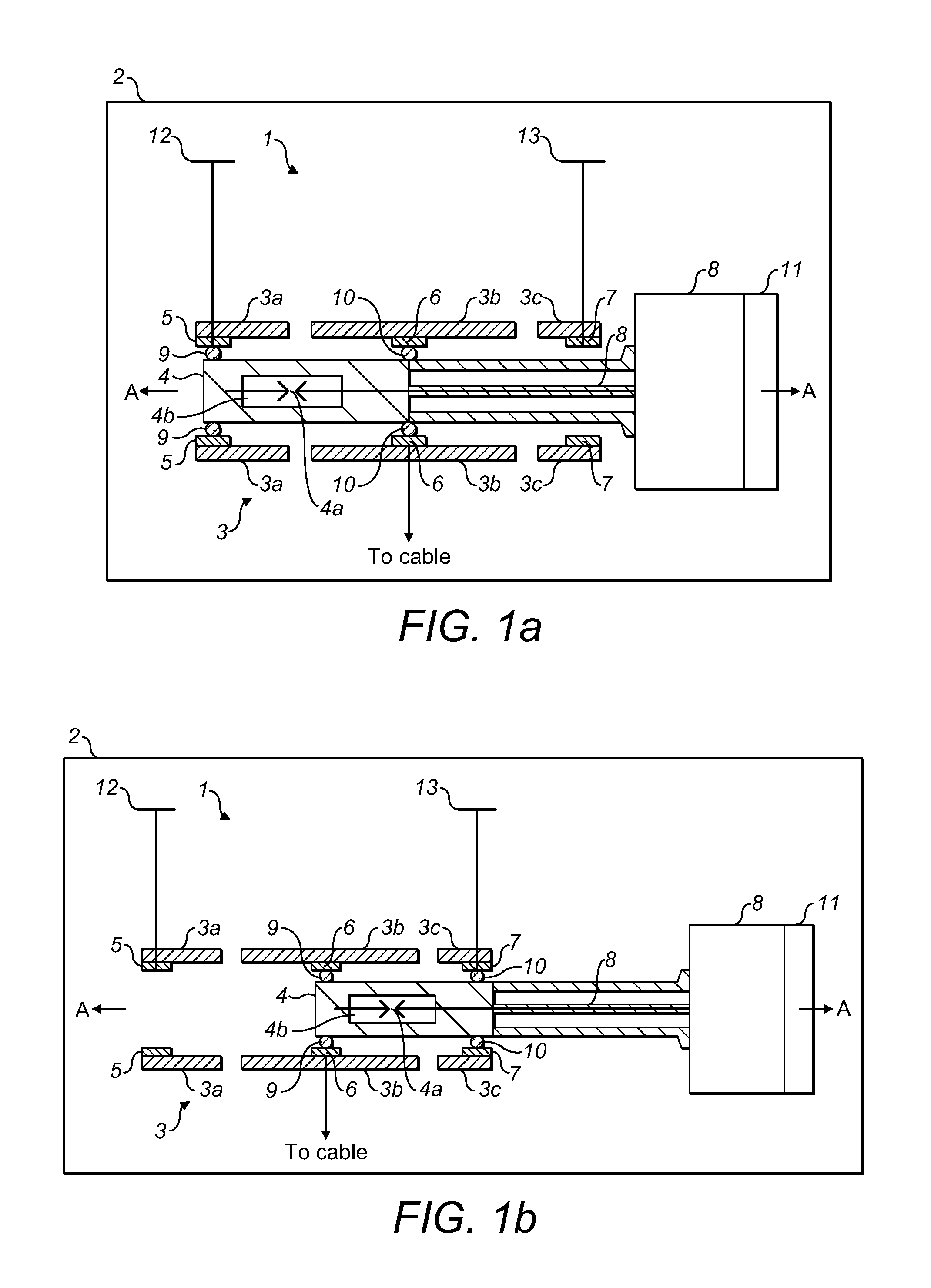
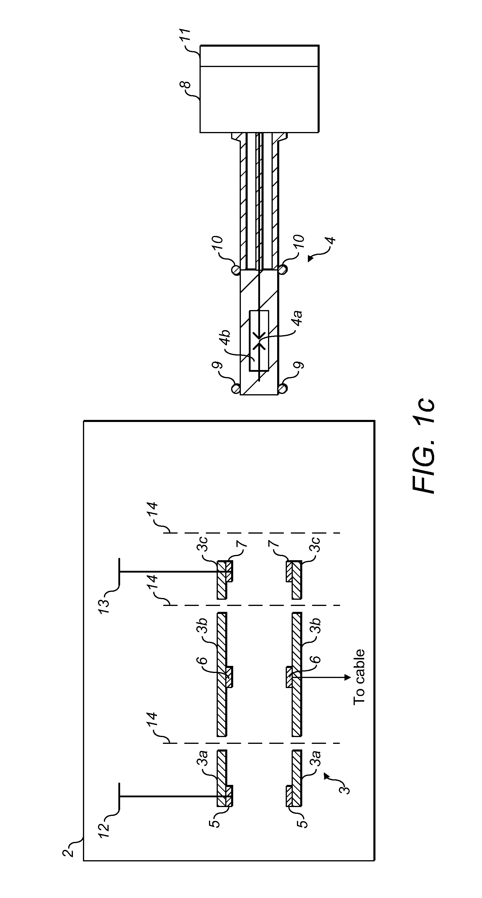
[0024]Referring to FIGS. 1a to 1c, a switch arrangement 1 for an electrical switchgear 2 comprises an electrical pole or terminal 3 and a circuit breaker switching element 4. The terminal 3, is fixed within the switchgear 2 and comprises a housing made up of first 3a, second 3b and third 3c electrically insulating tubular sections of substantially equal internal diameter which are spaced apart lengthwise along a common axis A. The three tubular sections may for example be formed of an epoxy resin material. Each of the three tubular sections 3a, 3b and 3c has a respective electrical contact 5, 6, 7 located inside of it. The first section 3a has a first bus bar contact 5 in electrical connection with a first electrical bus 12 of the switchgear 2, the second section 3b has a cable contact 6 in electrical connection with a cable (not shown) of the switch gear 2 and hence to a load (not shown) and the third section 3c comprises a second bus bar contact 7 in electrical connection with a s...


PUM


Abstract

A switch arrangement for an electrical switchgear comprising a first bus, a second bus and a load connection. The switch arrangement comprises a breaker; wherein said breaker is moveable in said switchgear between a first position and a second position, such that in use, when said breaker is in said first position and closed it electrically connects said first bus to said load connection, and when said breaker is in said second position and closed it electrically connects said second electrical bus to said load connection, with said first electrical bus disconnected from said load connection.

Description

BACKGROUND[0001]1. Field[0002]The disclosed concept relates to a switch arrangement for electrical switchgear.[0003]2. Background Information[0004]As is well known, switchgear is an integrated assembly of switches, circuit breakers, buses (i.e. power supply rails), fuses and other components used to isolate electrical equipment at an electrical installation, for example, an electrical power substation. Switchgear is used to both de-energise equipment to allow work to be done and to clear faults downstream of the switchgear. Switchgear is often housed in a metal cabinet at the installation.[0005]In known installations, a distinction is made between so called ‘fixed switchgear’ and so called ‘withdrawable switchgear’. In fixed switchgear the main switching / protective device, for example a circuit breaker, is fastened within the installation by fasteners, for example bolts, and cannot be removed from the installation without using tools to undo the fasteners. In withdrawable switchgear...

Claims


Application Information

Patent Timeline
Patent Type & Authority Applications(United States)
IPC IPC(8): H02B1/20
CPCH02B11/06
Inventor ABRAHAMSEN, MICHAEL H.BEAVER, JON C.YANNIELLO, ROBERT
Owner EATON INTELLIGENT POWER LIMITED
Why Eureka
Try Eureka