Method of servicing a gas turbine engine

a gas turbine engine and service method technology, applied in the direction of machines/engines, sustainable transportation, mechanical equipment, etc., can solve the problems of difficult and/or time-consuming, or not even possible, to only remove the required part, relatively straightforward to only remove the relevant rigid raft assembly, etc., to reduce the total number of anti-vibration mounts that are required to assemble an engine, and to prolong the life of the rigid raft assembly.

Active Publication Date: 2016-02-16
ROLLS ROYCE PLC
View PDF127 Cites 9 Cited by
  • Summary
  • Abstract
  • Description
  • Claims
  • Application Information

AI Technical Summary

Benefits of technology

[0018]Replacing a first rigid raft assembly with a pre-prepared second rigid raft assembly may significantly reduce the out-of-service time of the gas turbine engine being serviced. The second rigid raft assembly may be prepared and optionally tested, for example whilst the first rigid raft assembly is still operational on the gas turbine engine. Furthermore, as discussed elsewhere herein, the assembly / disassembly of rigid raft assemblies, such as electrical harness raft assemblies and / or dressed rigid raft assemblies (described in greater detail below), may be particularly quick and straightforward, for example compared with conventional electrical harnesses and / or engine dressings.
[0065]Furthermore, components that are conventionally mounted to an engine without anti-vibration mounts (for example because of the weight and / or cost penalty), but which are now mounted to a rigid raft assembly, may benefit from vibration isolation without any weight / cost / assembly time penalty. This may reduce the possibility of damage occurring to such components and / or increase their service life. Such components may include, for example, ignitor boxes (used to provide high voltage power to engine ignitors), and pressure sensors / switches, for example for fluid systems such as oil, air, fuel, pneumatics and / or hydraulics.

Problems solved by technology

It may be difficult and / or time consuming, or not even possible, to only remove the required part of a conventional component / system from a gas turbine engine.
However, it may be relatively straightforward to only remove the relevant rigid raft assembly, for example by simply disconnecting it from the engine and any other rigid raft assemblies / components to which it is connected.

Method used


Image

  • Method of servicing a gas turbine engine
  • Method of servicing a gas turbine engine
  • Method of servicing a gas turbine engine

Examples


Embodiment Construction

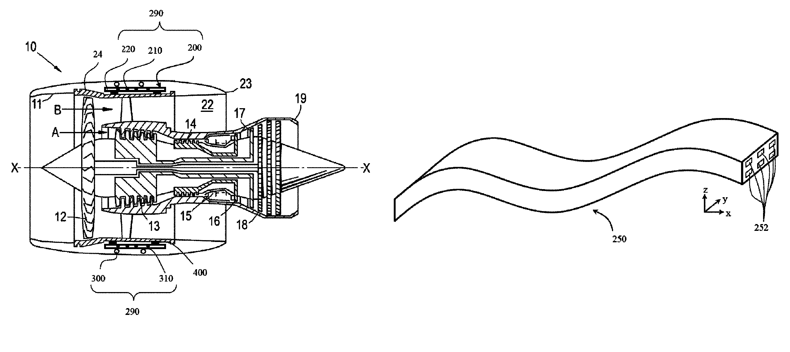
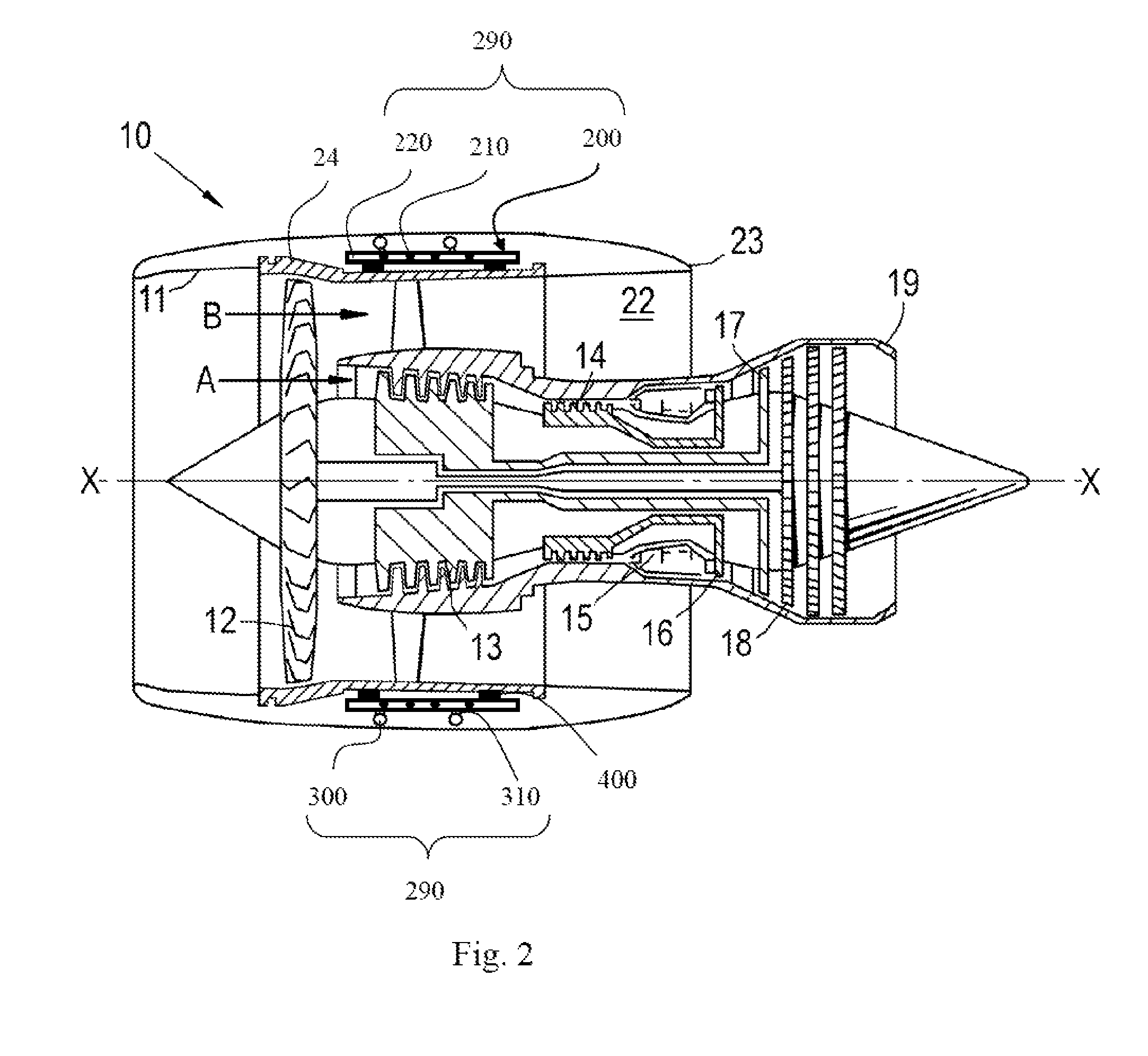
[0083]With reference to FIG. 2, a ducted fan gas turbine engine generally indicated at 10 has a principal and rotational axis X-X. The engine 10 comprises, in axial flow series, an air intake 11, a propulsive fan 12, an intermediate pressure compressor 13, a high-pressure compressor 14, combustion equipment 15, a high-pressure turbine 16, and intermediate pressure turbine 17, a low-pressure turbine 18 and a core engine exhaust nozzle 19. The engine also has a bypass duct 22 and a bypass exhaust nozzle 23.

[0084]The gas turbine engine 10 works in a conventional manner so that air entering the intake 11 is accelerated by the fan 12 to produce two air flows: a first air flow A into the intermediate pressure compressor 13 and a second air flow B which passes through the bypass duct 22 to provide propulsive thrust. The intermediate pressure compressor 13 compresses the air flow A directed into it before delivering that air to the high pressure compressor 14 where further compression takes...


PUM

PropertyMeasurementUnit
lengthaaaaaaaaaa
pressureaaaaaaaaaa
flexibleaaaaaaaaaa

Abstract

A gas turbine engine 10 is provided with rigid raft assemblies 290, which may be electrical harness raft assemblies 290 comprising electrical conductors embedded in a rigid composite material. The rigid raft assemblies 290 can be provided with engine dressings, such as pipework and ECUs to produce an electrical raft assembly. In order to assemble or dress the gas turbine engine 10, the rigid raft assemblies can be pre-prepared to incorporate at least a part of at least one gas turbine engine system / component before being installed on the gas turbine engine 10. During maintenance, whole raft assemblies can be removed and replaced with corresponding, pre-prepared assemblies. This can save considerable time during engine build and maintenance.

Description

CROSS-REFERENCE TO RELATED APPLICATIONS[0001]This application is based upon and claims the benefit of priority from British Patent Application Number GB1122143.9 filed 22 Dec. 2011, the entire contents of which are incorporated by reference.BACKGROUND OF THE INVENTION[0002]1. Field of the Invention[0003]This invention relates to assembly and maintenance of gas turbine engines. In particular, aspects of the invention relate to the use of pre-prepared rigid raft assemblies in the assembly and / or servicing of a gas turbine engine.[0004]2. Description of the Related Art[0005]A typical gas turbine engine comprises a number of components and / or systems that need to be attached thereto in order for the gas turbine engine to function in the intended manner. Such systems and / or components include, for example, fluid systems, electrical systems, monitoring systems and various electronic control units. These systems / components may be referred to as auxiliary (or ancillary) components / systems, ...

Claims


Application Information

Patent Timeline
Patent Type & Authority Patents(United States)
IPC IPC(8): B23P6/00F02C7/32
CPCB23P6/005F02C7/32Y02T50/672Y10T29/49238F05D2230/60F05D2230/72F05D2230/70Y02T50/60F02C7/00F02C7/20
Inventor BROUGHTON, PAULPEACE, RICHARD
Owner ROLLS ROYCE PLC
Why Eureka
Try Eureka