Laying Aid for Tiles

a technology for laying aids and tiles, applied in the direction of flooring, instruments, constructions, etc., can solve the problems of inconvenient use, lack of stability, and inability to assist in achieving the uniformity of tile coverings, and achieve the effects of high surface hardness, high modulus of elasticity, and resistance to customary tile adhesives

Inactive Publication Date: 2012-02-02
BRINKMAN SILKE +1
View PDF3 Cites 16 Cited by
  • Summary
  • Abstract
  • Description
  • Claims
  • Application Information

AI Technical Summary

Benefits of technology

[0022]In another advantageous embodiment of the invention, the laying aid device is formed from an essentially inflexible and / or transparent plastic material, in particular ABS, PC, SAN, or polystyrene. When a transparent material is selected in one preferred embodiment of the invention, according to the invention this has the advantage that the laying aid, which is intended to remain in the finished tiled surface, is essentially invisible, even when a transparent joint compound such as silicone is used. The plastics polystyrene, acrylonitrile butadiene styrene (ABS), polycarbonate (PC), and styrene acrylonitrile (SAN) are characterized by high surface hardness, resistance to customary tile adhesives, and a high modulus of elasticity, for example in the range of 2000 MPa and greater.

Problems solved by technology

A disadvantage of the known jointing crosses is that they do not provide stability during the laying, i.e., before the tile grout sets.
A further disadvantage of this simplest previously known type of laying aid for tile work is that it does not assist in achieving evenness of the tile covering.
However, in these known laying aids it is disadvantageous that they are very inconvenient to use, since by principle they must extend over the dimensions of multiple tiles.
A further disadvantage is that this known laying aid may even have to have a surface which corresponds to the floor to be laid, which is particularly inconvenient.
In addition, the large-surface structure of the known laying aid has the disadvantage that large regions of the tiles or plates to be laid are not wetted by adhesive due to the fact that they are covered by the reinforcing webs running diagonally or parallel with respect to the lattice bars.
This may disadvantageously result in insufficient bonding and adhesion of the tiles to the subsurface.
A disadvantage of this known laying aid for tile work is that it, too, may be impractical to use due to the dimensions, which correspond to the surface area of multiple tiles, or even to the entire area to be laid.
In addition, use of the interwoven lattice, which runs continuously between the floor and the underside of the tiles, entails the risk that adhesion of the tiles to the floor may be impaired due to the fact that the wetting of the tiles with tile adhesive is interrupted.

Method used


Image

  • Laying Aid for Tiles
  • Laying Aid for Tiles
  • Laying Aid for Tiles

Examples


Embodiment Construction

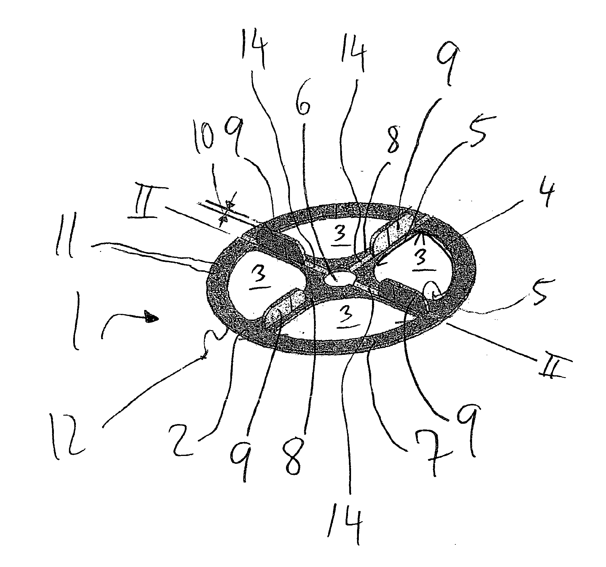
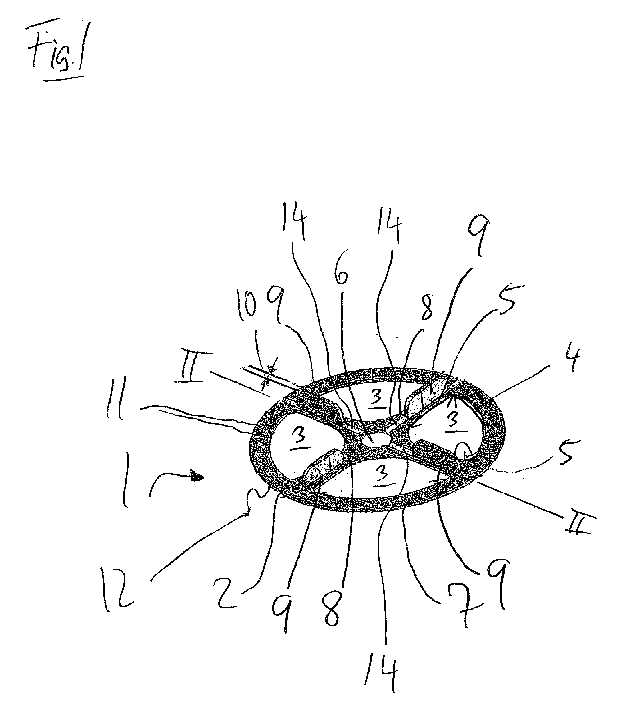
[0032]FIG. 1 shows a perspective view, in an oblique angle from the top, of one preferred embodiment of a laying aid 1 according to the invention, having a tile-supporting region 2. Overall, the laying aid 1 has a disk shape with a circular contour. The tile-supporting region 2 is interrupted by four identical cutouts 3. The cutouts 3 essentially have the shape of a sector of a circle, i.e., a circular surface, which is delimited by a circular arc 4 and two circle radii 5. The corners of the circular sector are rounded.

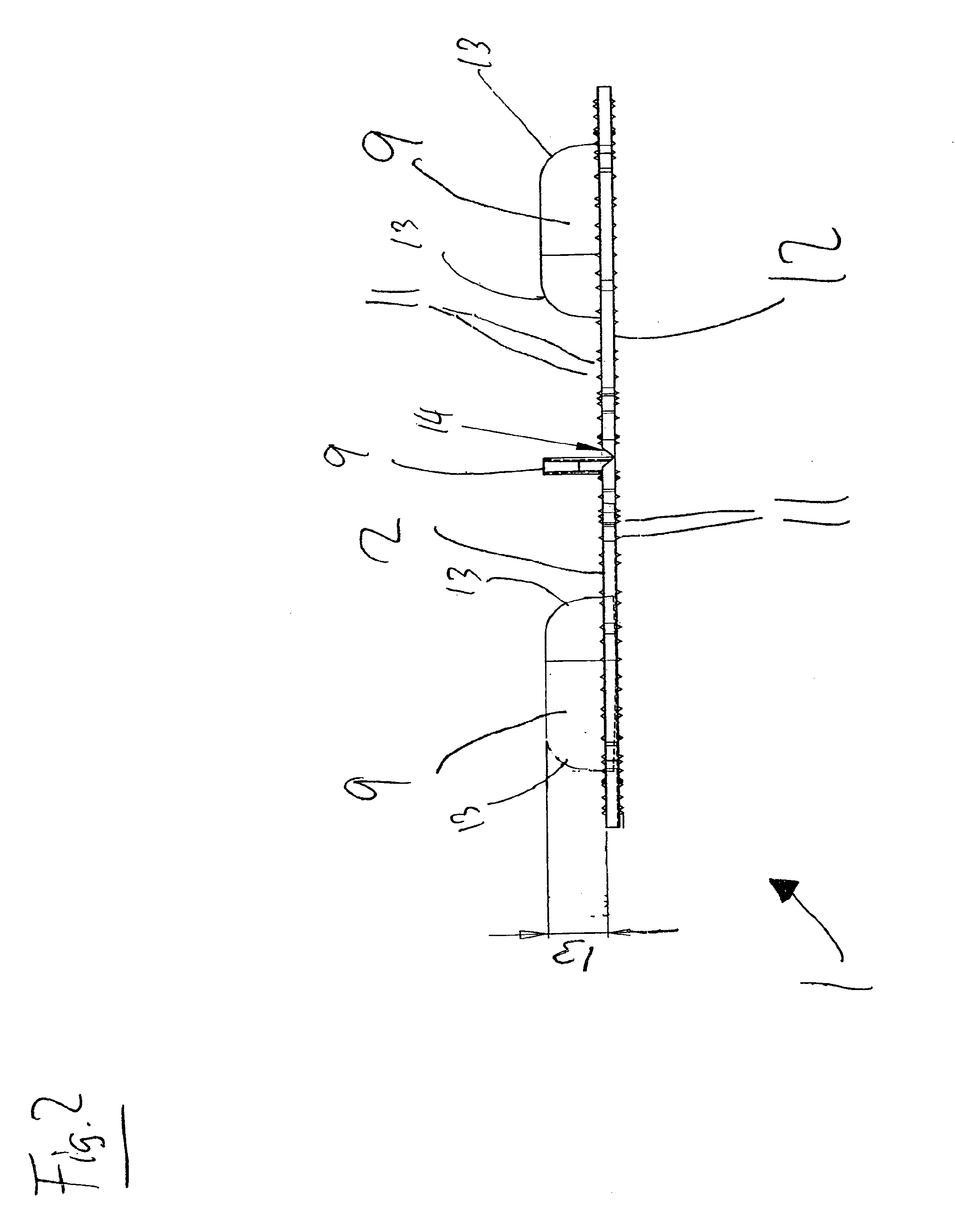
[0033]A circular cutout 6 is present in the center of the laying aid 1. Thus, the tile-supporting region 2 is composed of an annular section 7 and four spoke-like sections 8 which are oriented at an angle of 90° relative to one another. A spacer web 9 is situated on each spoke-like section 8. Each spacer web 9 is situated at the level of the cutouts 3 in the radial direction with respect to the spoke-like section 8. The height of each spacer web 9 extends perpendicula...


PUM


Abstract

The invention relates to a device (1) used as a laying aid for tiling work, comprising a base element (7, 8) having a support region (12) for laying flat on a surface to be covered with tiles (16), and a tile-supporting region (2) on which tiles (16) are placed. The tile-supporting region (2) has at least two web-like spacer elements (9) which extend perpendicularly with respect to a plane defined by the tile-supporting region (2) and which are arranged at an angle of an integer multiple of 90° relative to one another in said plane, and which have a thickness (10) corresponding to a desired joint spacing. To avoid the disadvantages of the known laying aids and to achieve uniform joint spacing and an even surface, whereby the laying aid is intended to be especially easy to handle, the base element (7, 8) is designed as a disk-like element having a base area that is smaller than a base area of the tiles (16) to be laid.

Description

CROSS REFERENCE TO RELATED APPLICATIONS[0001]This application is the National Phase Application under 35 USC §371 of International Application No. PCT / EP2010 / 005953, filed Sep. 30, 2010, which claims priority to German Patent Application 10 2009 043 465.8, filed Sep. 30, 2009.BACKGROUND[0002]A. Technical Field[0003]The present invention relates to a device used as a laying aid for tile work, comprising a base element having a support region for laying flat on a surface to be covered with tiles, and a tile-supporting region on which tiles are placed, the tile-supporting region having at least two web-like spacer elements which extend perpendicularly with respect to a plane defined by the tile-supporting region and which are arranged at an angle of an integer multiple of 90° relative to one another in said plane, and which have a thickness corresponding to a desired joint spacing.[0004]B. Background of the Invention[0005]Laying aids of the above-mentioned type for tile work are used t...

Claims


Application Information

Patent Timeline
Patent Type & Authority Applications(United States)
IPC IPC(8): G01B1/00
CPCE04F2015/02116E04F15/02022E04F15/02005E04F21/22
Inventor HILLEBRANDT, WOLFGANG
Owner BRINKMAN SILKE
Why Eureka
Try Eureka