

Wireless power transmission unit and power generator with the wireless power transmission unit
a power transmission unit and wireless technology, applied in the direction of transformers, electromagnetic wave systems, inductances, etc., can solve the problems of too high cost of manufacturing too high cost of establishing such a system by installing those cells and modules, etc., to reduce the cost of installing the power generator, increase the voltage significantly, and increase the voltage
- Summary
- Abstract
- Description
- Claims
- Application Information
AI Technical Summary
Benefits of technology
Problems solved by technology
Method used
Image

Examples
embodiment 1
[0088]First of all, a First Specific Preferred Embodiment of a power generator according to the present invention will be described with reference to FIGS. 12 and 13. Specifically, FIG. 12 is a perspective view schematically illustrating the first preferred embodiment of the present invention and FIG. 13 is an equivalent circuit diagram of the wireless transmission section 105 shown in FIG. 12. In FIGS. 12 and 13, any component having substantially the same function as its counterpart shown in FIGS. 5 and 6 is identified by that counterpart's reference numeral.
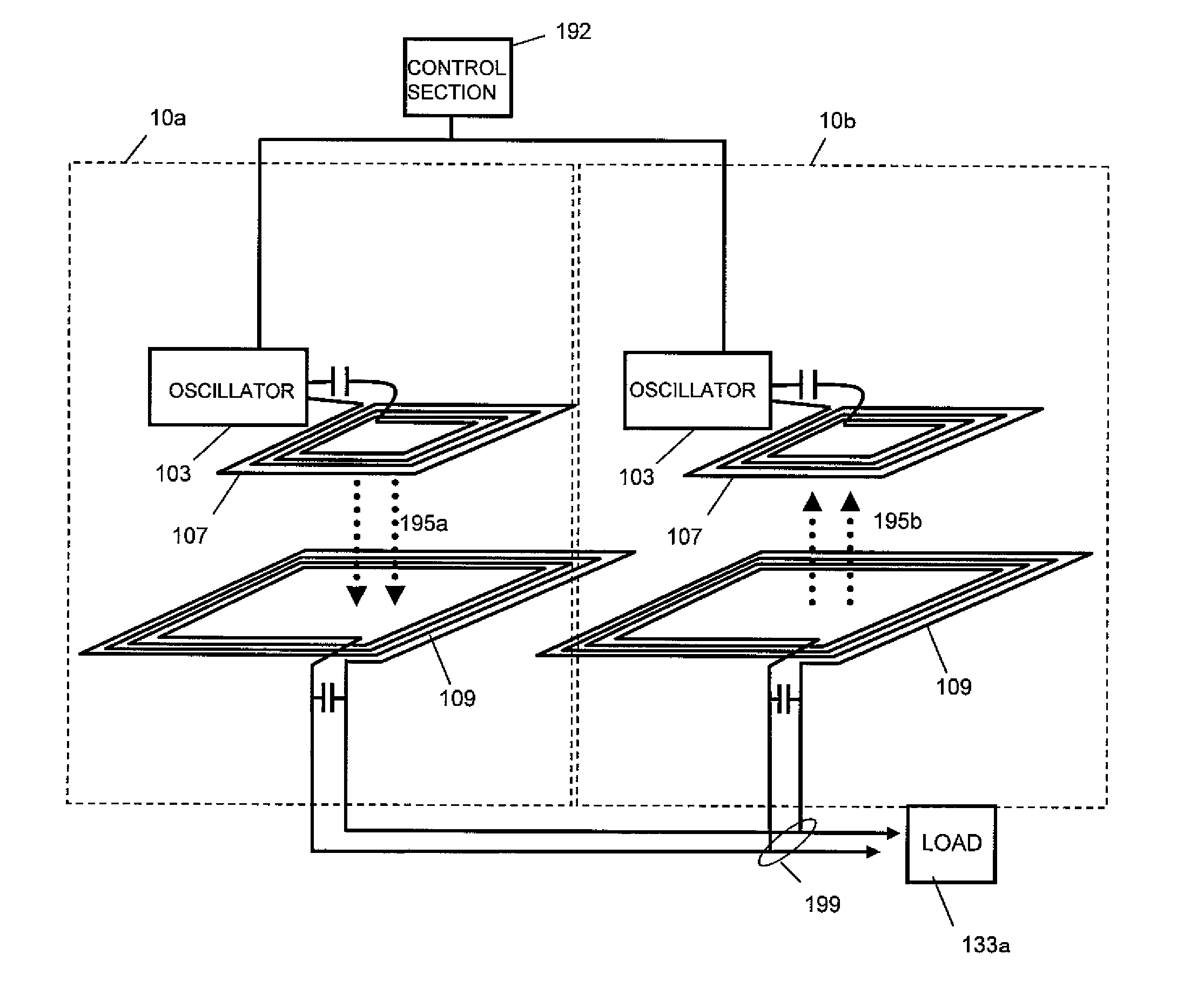
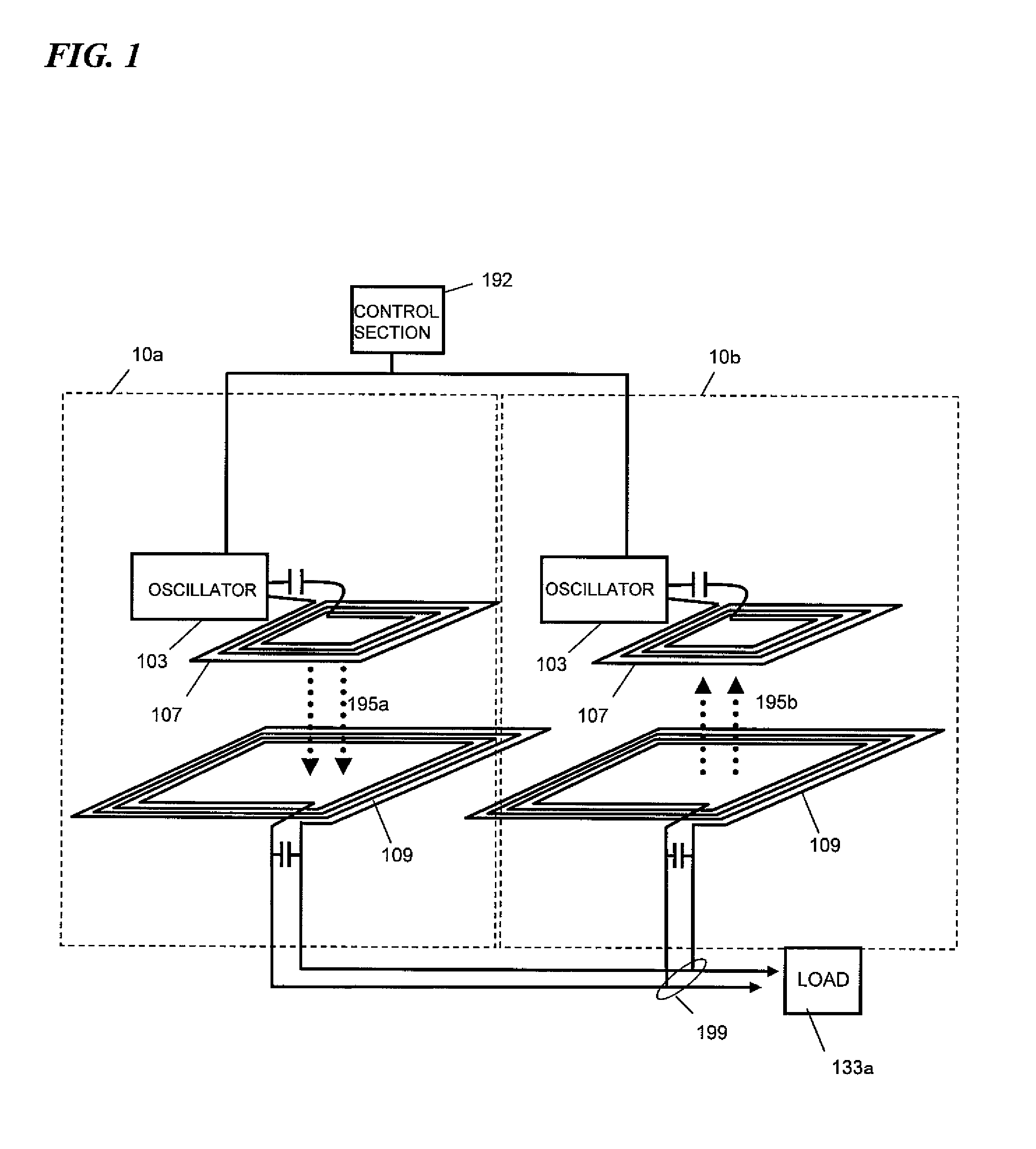
[0089]As shown in FIG. 7, the power generator of this preferred embodiment includes multiple power generating units, of which the outputs are connected in parallel with each other. Each of the power generating units includes a power generating section 101, an oscillator 103 and a wireless transmission section 105, which are connected together in series as shown in FIG. 12.
[0090]In this preferred embodiment, the power generatin...
embodiment 2
[0152]Hereinafter, a second preferred embodiment of a power generator according to the present invention will be described with reference to FIG. 19.
[0153]In the power generator of this second preferred embodiment, a rectifier 115 for converting RF energy into DC energy is connected in series so as to follow the combining section 199, which is a primary difference from the power generator of the first preferred embodiment described above. By adopting such a configuration, the energies that have been received by multiple power receiving antennas 109 can be output as DC energy.
[0154]The power generator of this preferred embodiment can also achieve the same effects as what is achieved by the counterpart of the first preferred embodiment. In addition, DC power can be obtained as output according to this preferred embodiment.
[0155]To reduce multiple reflection of the RF energy between the circuit blocks and to improve the overall power generation efficiency, when the output terminal of t...
embodiment 3
[0162]Hereinafter, another preferred embodiment of a power generator according to the present invention will be described with reference to FIG. 21, which is a block diagram illustrating a power generator as a third specific preferred embodiment of the present invention. In FIG. 21, any component having substantially the same function as its counterpart of the preferred embodiments described above is identified by that counterpart's reference numeral and a detailed description thereof will be omitted herein to avoid redundancies.
[0163]The power generator shown in FIG. 21 includes a number of power generating units 131a, 131b, . . . and 131n that are connected in parallel with each other. In this preferred embodiment, each of these power generating units 131a, 131b, . . . and 131n is the power generator of the second preferred embodiment described above. However, to achieve the effects of the present invention, at least two power generating units that are connected in parallel with e...
PUM
| Property | Measurement | Unit |
|---|---|---|
| output voltage | aaaaa | aaaaa |
| output voltage | aaaaa | aaaaa |
| electrical length | aaaaa | aaaaa |
Abstract
Description
Claims
Application Information