
Input device with ghost key suppression
a technology of input device and ghost key, which is applied in the field of input device, can solve the problems of increasing the cost of keyboard device, and achieve the effects of reducing manufacturing costs, less chance of judging errors, and faster operation
- Summary
- Abstract
- Description
- Claims
- Application Information
AI Technical Summary
Benefits of technology
Problems solved by technology
Method used
Image

Examples
Embodiment Construction
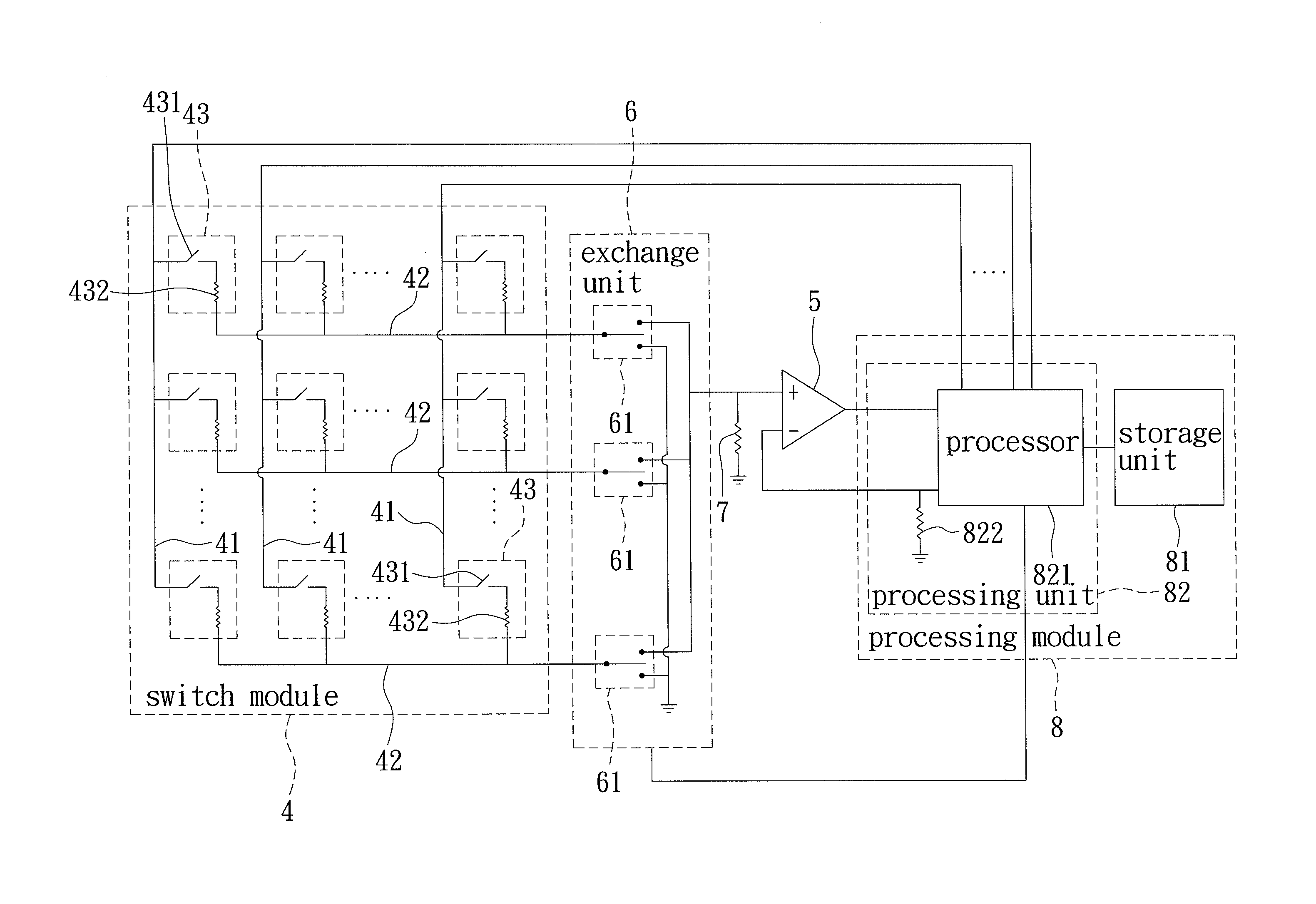
[0020]Referring to FIG. 4, the preferred embodiment of an input device with ghost key suppression according to the present invention is shown to include a switch module 4, a comparator 5, an exchange unit 6, a bias voltage resistor 7 and a processing module 8.
[0021]The switch module 4 includes a plurality of strobe lines 41, a plurality of sense lines 42, and a plurality of switch units 43. Each of the switch units 43 has a switch 431 and a resistor 432 connected in series between a corresponding one of the strobe lines 41 and a corresponding one of the sense lines 42. The switch 431 of each switch unit 43 is operable at a selected one of conducting and non-conducting states.
[0022]The comparator 5 includes a first input end, a second input end for receiving a reference signal, and an output end for outputting a comparison signal. The comparator 5 is configured for comparing a signal received at the first input end with the reference signal for generating the comparison signal. In th...
PUM
 Abstract
Description
Claims
Application Information