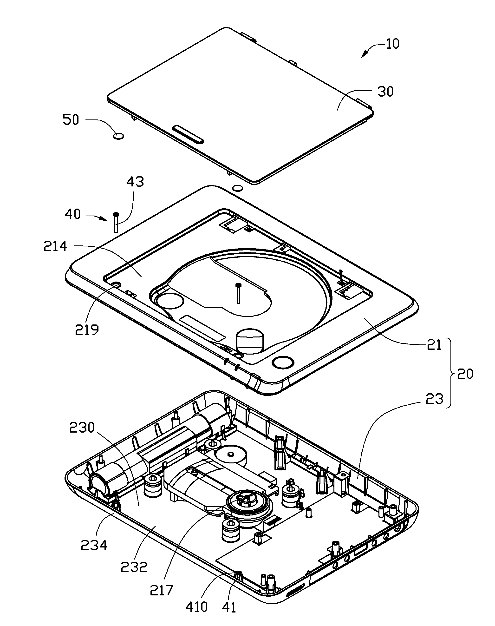
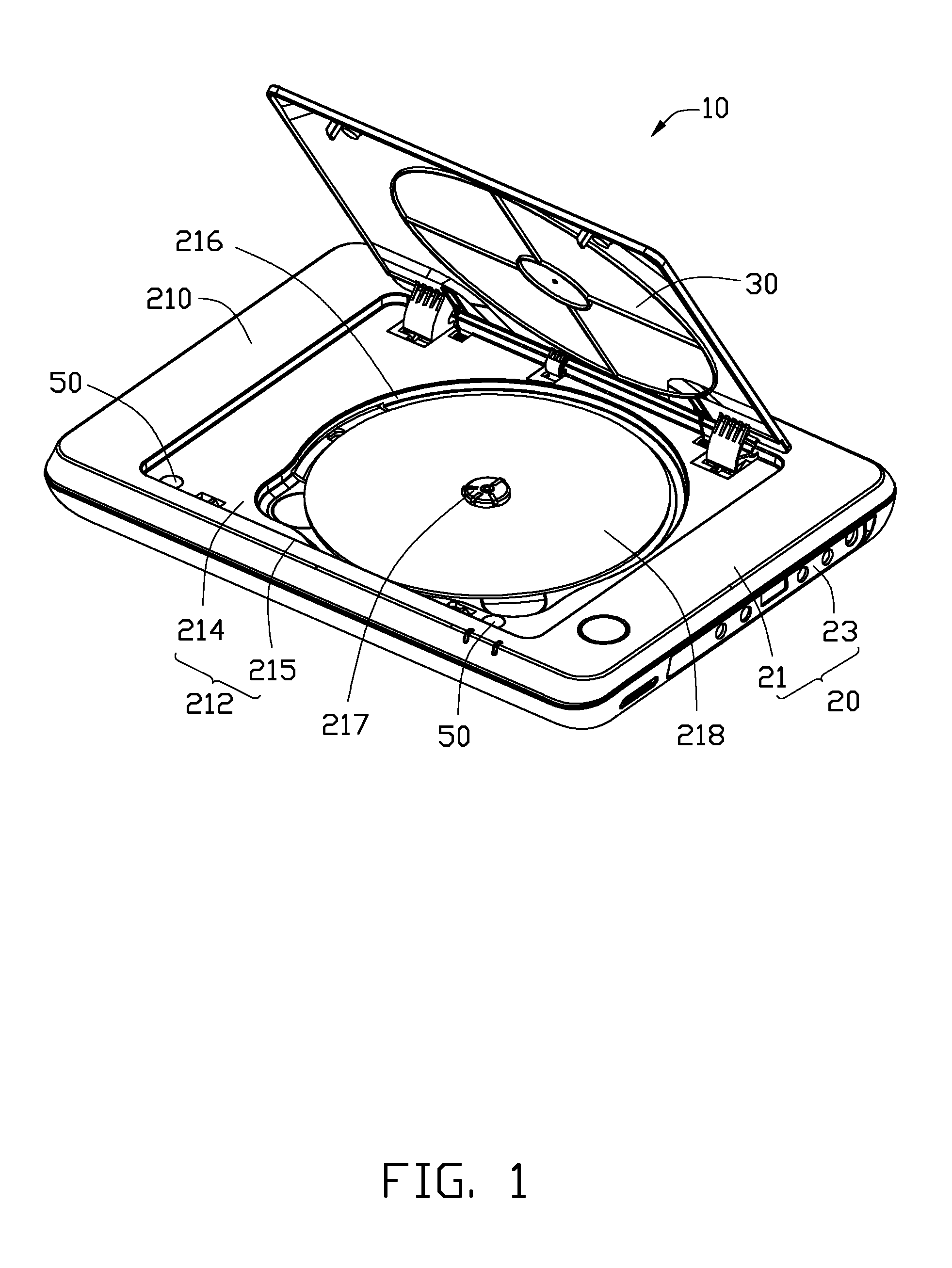
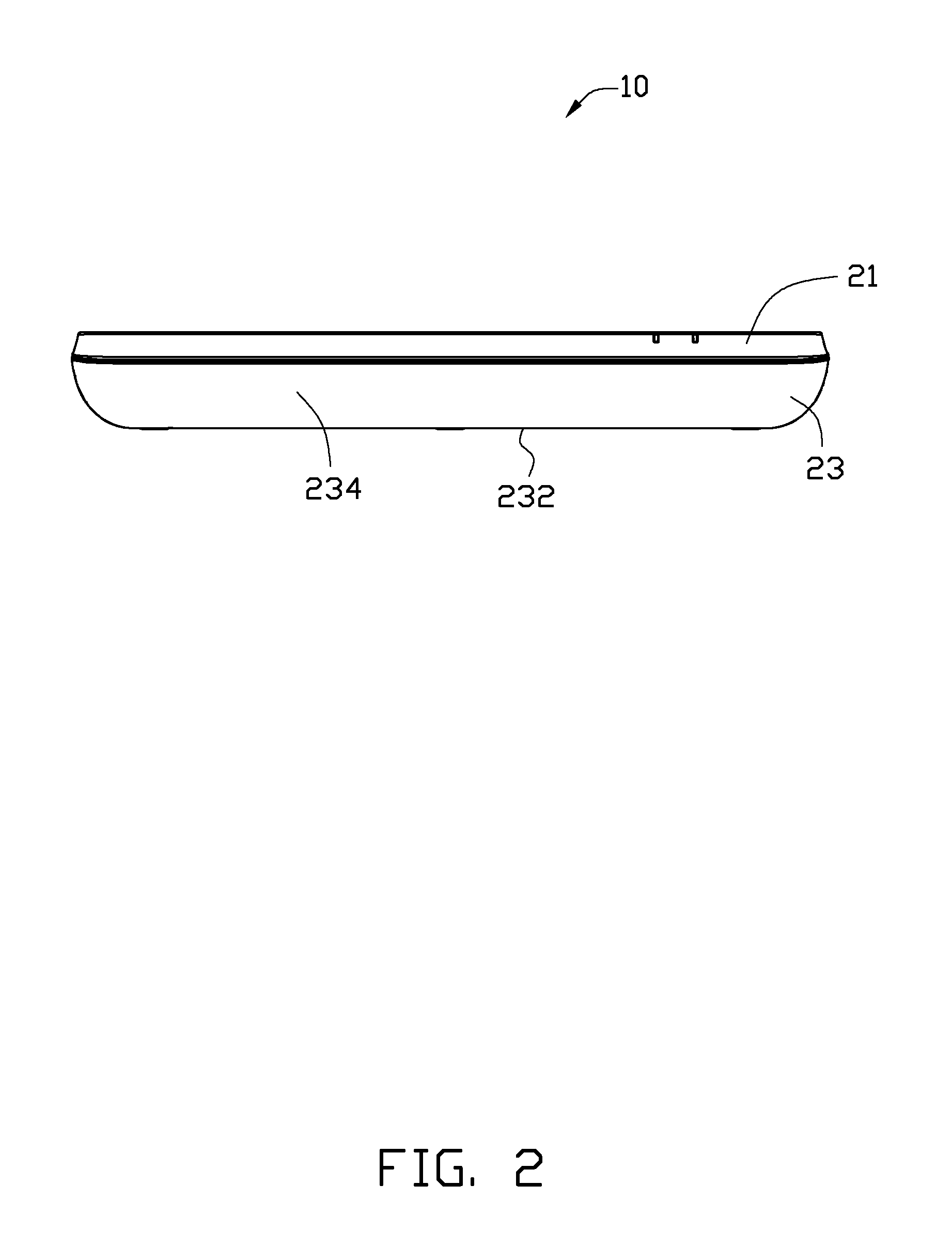
[0011]Referring to FIG. 1, an electronic device 10 in accordance with an embodiment includes a housing 20 and a lid 30 pivotally connected to the housing 20. The housing 20 is used for accommodating various components of the electronic device 10. The lid 30 covers a part of the housing 20. In the illustrated embodiment, the electronic device 10 is an optical disk player, and the lid 30 covers a disk clipped in the housing 20.
[0012]In the illustrated embodiment, the housing includes an upper housing 21 and a lower housing 23 attached to the upper housing 21. A first depression 212 is defined in a top surface 210 of the upper housing 21 for accommodating the lid 30. The first depression 212 includes two walls 214 and 215. A second depression 216 is defined in the wall 214 with a rotator 217 located therein. A disk 218 is clipped on the rotator 217 and is received in the second depression 216. Referring also to FIG. 4, two connection holes 219 are defined in the wall 214 of the first depression 212, adjacent to the wall 215.
[0013]Also referring to FIGS. 2 and 3, the lower housing 23 includes a bottom wall 232 and a side wall 234 extending upwards from the bottom wall 232. In the illustrated embodiment, the side wall 234 is convexly curved and arc shaped.
[0014]Referring also to FIG. 4, the electronic device 10 further includes two connection structures 40 for connecting the upper housing 21 to the lower housing 23. Each connection structure 40 includes a connection post 41 connected to the lower housing 23 with a connection member 43 passing through the connection hole 219 defined in the upper housing 21 to be connected to the connection post 41. Each connection post 41 protrudes upwards from an interior surface of the side wall 234 of the lower housing 23 and is substantially perpendicular to the bottom wall 232. A screw hole 410 is defined in each connection post 41. Each connection member 43 is inserted in the corresponding connection hole 219 to extend into the screw hole 410 of the corresponding connection post 41. In some embodiments, the connection members 43 may be screws adapted to screw into the connection posts 41 respectively.
[0015]Referring to both FIGS. 1 and 4, the electronic device 10 further includes two covering members 50 disposed on the upper housing 21 corresponding to the connection holes 219 covering the connection members 43 respectively disposed in the connection holes 219. In the embodiment, the covering members 50 are made of elastic material.
[0016]The connection posts 41 protrude from the interior space of the side wall 234 of the lower housing 23. The connection holes 219 are defined in the wall 214 of the first depression 212, and the covering members 50 cover the connection members 41, therefore, the connection members 43 are invisible to users when users look at the side wall 234 or even the wall 214 of the first depression 212 of the upper housing.
[0017]It is to be understood, however, that even though information and advantages of the present embodiments have been set forth in the foregoing description, together with details of the structures and functions of the present embodiments, the disclosure is illustrative only; and that changes may be made in detail, especially in matters of shape, size, and arrangement of parts within the principles of the present embodiments to the full extent indicated by the broad general meaning of the terms in which the appended claims are expressed.