Telescopic cranial bone screw

a cranial bone screw and telescopic technology, applied in the field of telescopic cranial bone screws, can solve the problem that the plate does not allow the bone flap to move inward inside the cranium, and achieve the effect of preventing the flap from moving inside the cranial cavity

Active Publication Date: 2012-06-28
KHANNA ROHIT
View PDF7 Cites 15 Cited by
  • Summary
  • Abstract
  • Description
  • Claims
  • Application Information

AI Technical Summary

Benefits of technology

[0011]The present invention relates to a cranial fixation device for fixing a bone flap to the skull following a craniotomy. It also provides for constrained outward movement of the bone flap to immediately accommodate for an increase in intracranial pressure and subsequently allowing for the bone flap to move inwards up to the skull once the intracranial pressure normalizes.
[0014]Rather than providing a fixed locked position once implanted as described in all the cranial fixation devices in the prior art, the current invention allows for constrained outward movement of the bone flap relative to the skull in cases of cerebral swelling and subsequently retracts the bone flap against the skull once the swelling subsides.

Problems solved by technology

The plate does not allow the bone flap to move inward inside the cranium below the skull level.

Method used


Image

  • Telescopic cranial bone screw
  • Telescopic cranial bone screw
  • Telescopic cranial bone screw

Examples


Embodiment Construction

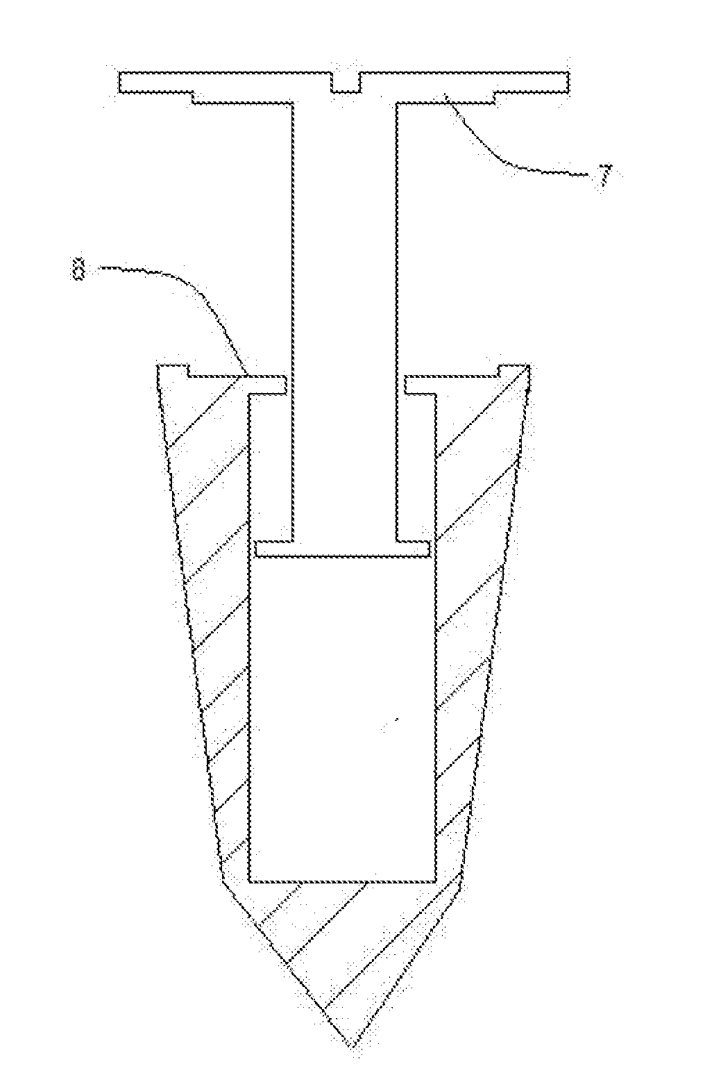
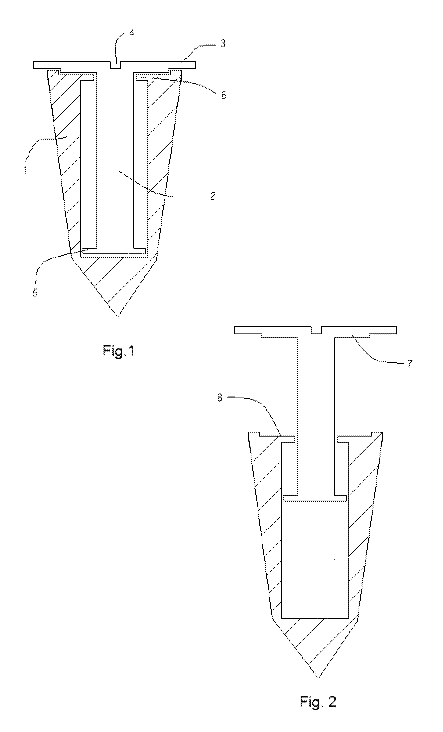
[0084]FIGS. 1 and 2 illustrate a telescopic screw with a housing component 1 and a telescopic component 2. The telescopic component at one end has a head with a recess 4 and a widened portion 3 and at the other end has extensions 5. The telescopic component 2 is contained inside the housing component 1. The housing component has extensions 6 and a recess 8. The screw is drilled into the skull with a screwdriver attached to the recess 4. FIG. 1 illustrates the telescopic screw in a retracted position with the wider head portion 3 engaged with the recess 8 to provide a locking mechanism. FIG. 2 illustrates the screw placed in an extended position by an increase in the intracranial pressure. The telescopic component extension 5 and the housing component extension 6 prevent the telescopic component from pulling out from the housing component during a maximally extended position.

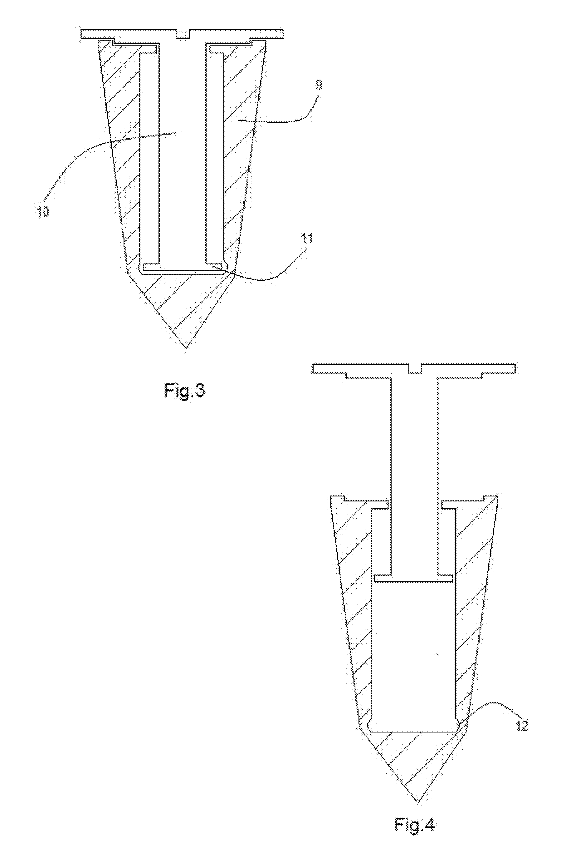
[0085]FIGS. 3 and 4 illustrate another embodiment of the telescopic screw. The telescopic component 10 has an ...


PUM


Abstract

The invention provides a method and apparatus for cranial fixation following a craniotomy and treatment for increased intracranial pressure. The cranial fixation device comprises of plates attached to the skull with a telescopic screw. The telescopic screw provides constrained movement of the bone flap relative to the skull to accommodate an increase in the intracranial pressure.

Description

BACKGROUND OF THE INVENTION[0001]Neurosurgery routinely involves performing craniotomies for exposure of the brain and intracranial contents for various intracranial pathologies including tumors, head injuries, vascular malformations, aneurysms, infections, hemorrhages, strokes, and brain swelling. A craniotomy involves creation of burr holes and removal of a portion of the skull (bone flap) with subsequent approximation of the bone flap for closure. Several methods and fixation devices are available for re-attaching the bone flap to the skull including small metallic or absorbable plates with screws or wires. Another method has been the use of cranial clamps consisting of two connected circular elements placed on the inside and outside surfaces of the skull. All of the aforementioned cranial fixation devices in the prior art provide for a rigid fixation of the bone flap to the skull.[0002]In cases of post-operative intracranial hemorrhage and / or brain swelling development, a decomp...

Claims


Application Information

Patent Timeline
Patent Type & Authority Applications(United States)
IPC IPC(8): A61B17/80A61B17/88
CPCA61B17/688A61B2017/00004A61B17/8685A61B17/8625
Inventor KHANNA, ROHIT
Owner KHANNA ROHIT
Why Eureka
Try Eureka