Blade snap-off holder

a blade and snap-off technology, applied in the field of blade snap-off holders, can solve the problems of user nervousness when the blade tip is snapped off, and achieve the effect of safe, easy and smooth blade snap-off operation, and easy snap-off with eas

Inactive Publication Date: 2012-08-09
OLFA
View PDF4 Cites 0 Cited by
  • Summary
  • Abstract
  • Description
  • Claims
  • Application Information

AI Technical Summary

Benefits of technology

[0008]That is, the user grips the holder in one hand and the cutter knife body in the other hand, with the blade tip inserted into the slit formed on the side wall of the holder, and then the user applies a bending force to the blade to snap off the tip. At that time, the bending force should be large to a certain degree, while subtle control of the force is needed, such that an excessive force would not cause the user's hands to hit on something and to be injured.
[0009]An object of the present invention is therefore to provide a blade snap-off holder, by which a safe, easy and smooth snapping-off operation can be achieved without any nervous caution.
[0017]According to the holder of the present invention constructed as above, a tip of a cutter knife blade can be easily snapped off with ease, only by inserting the cutter knife blade into the holder and operating the operation means to apply a bending force to the blade. During this operation of snapping-off, any subtle control of the force is not needed. In other words, a safe, easy and smooth blade snap-off operation can be achieved without a user's any nervous caution.
[0018]Further, the blade tips thus snapped off can be held in the holder without flying off, with no extra burden.

Problems solved by technology

In any of the conventional proposals, a user gets nervous a little when snapping off the blade tip.

Method used


Image

  • Blade snap-off holder
  • Blade snap-off holder
  • Blade snap-off holder

Examples


Embodiment Construction

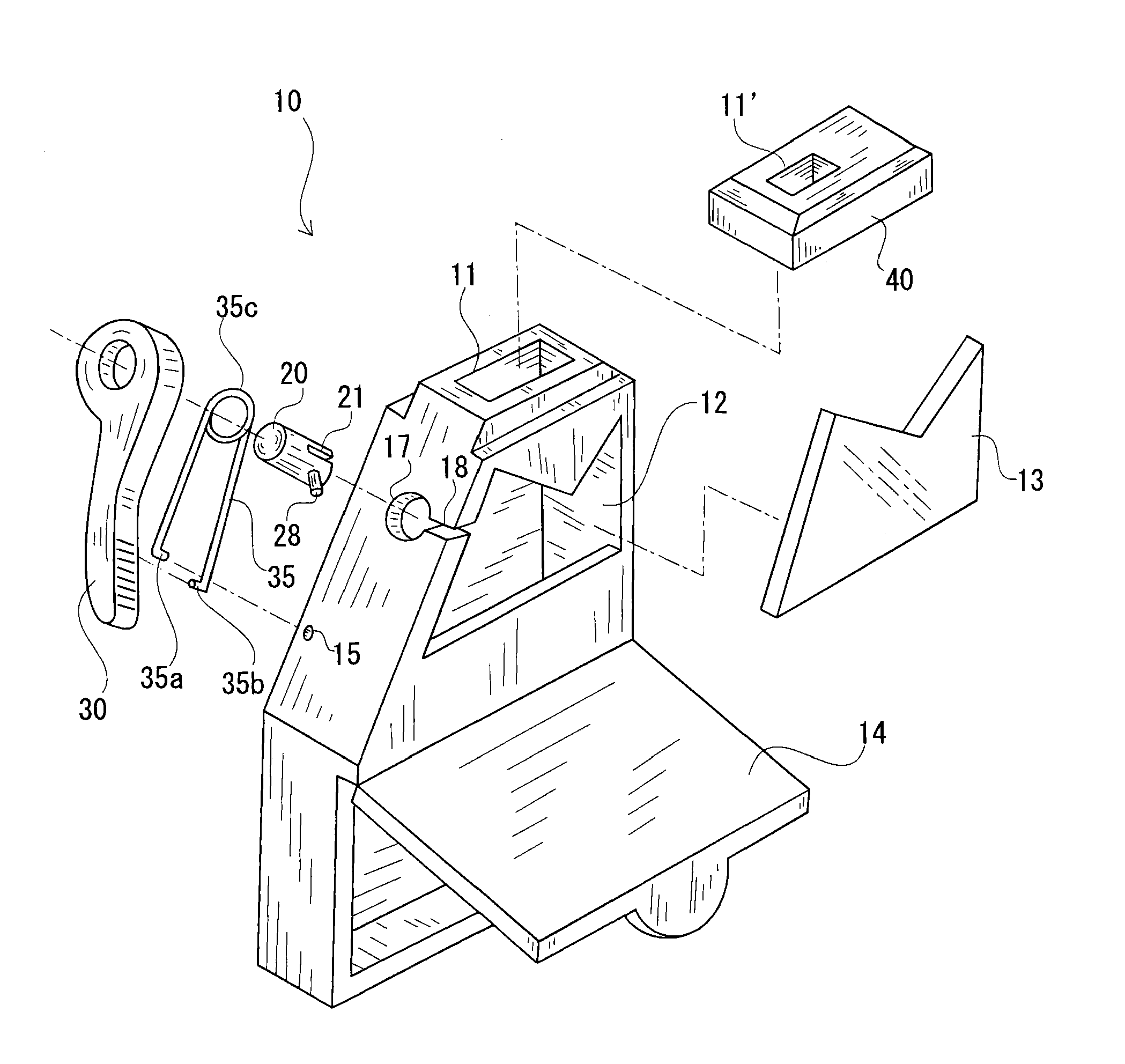
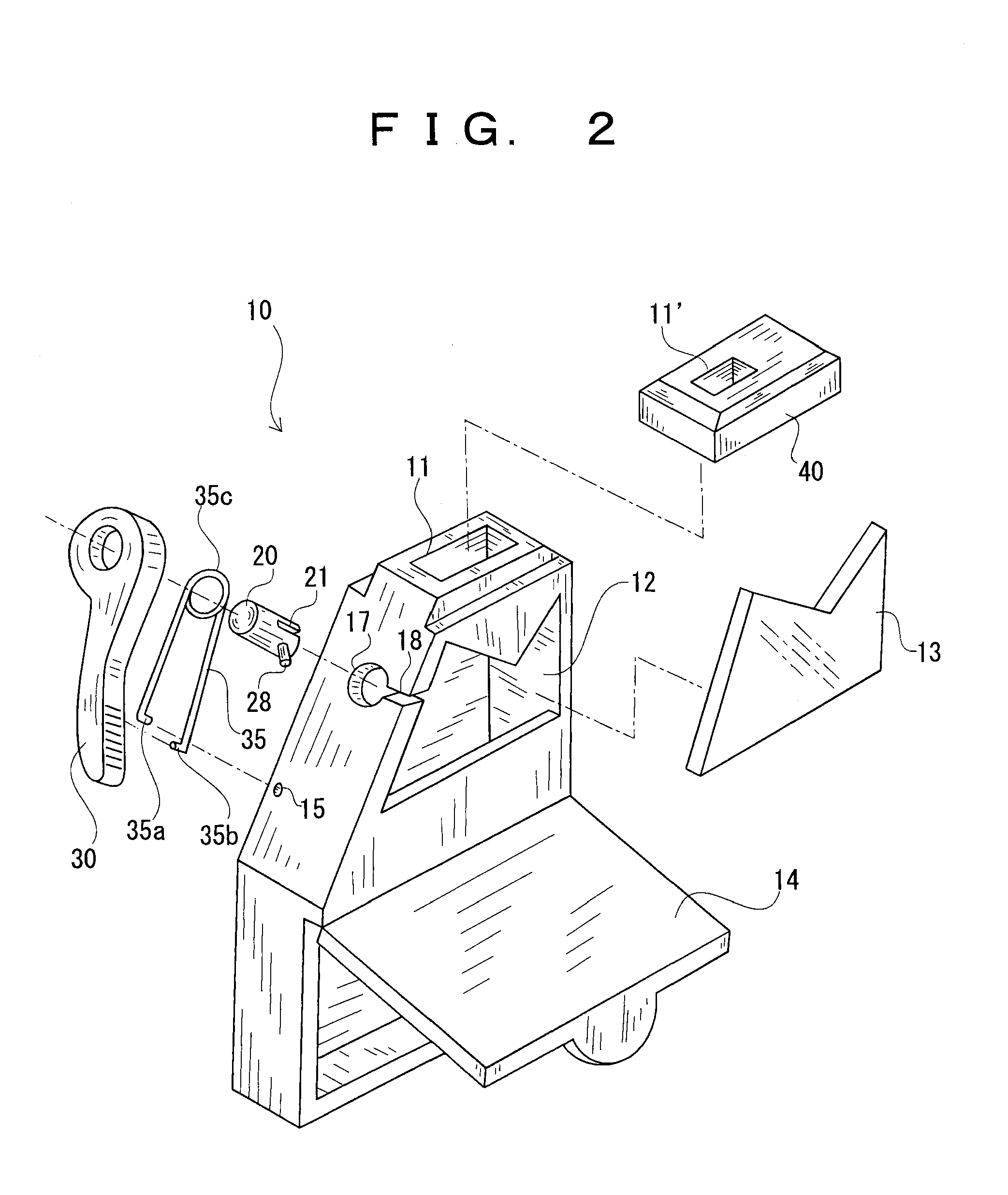
[0023]FIG. 2 shows an exploded perspective view of a blade snap-off holder 10 according to an embodiment of the present invention. As shown in FIG. 2, an insertion opening 11 is formed on the top wall of the holder 10. The tip of a knife blade is inserted into the opening 11 (see FIG. 3).

[0024]In FIG. 2, the rotary member 20 is cylindrically shaped and is rotatable about a rotational axis “A” (see FIG. 3). An adhesive, press fitting or other suitable means can be employed to secure the rotary member 20 to the operation lever 30, such that the rotary member 20 would not rotate relatively to the operation lever 30.

[0025]The rotary member 20 extends into the holder 10 through an opening 17 formed on the side wall of the holder 10, and is operated by the operation lever 30 which is located outside the holder 10.

[0026]When inserting the rotary member 20 into the opening 17, the pin 28 projected from the rotary member 20 is passed through a slit 18 formed on the holder 10, and then the sl...


PUM


Abstract

Disclosed is a blade snap-off holder which enables a safe, easy and smooth operation for snapping off a blade tip of a cutter knife. The holder has an insertion opening on its wall. A tip of a knife blade inserted through the opening is received in a groove of a rotary member located inside the holder. The rotation axis of the rotary member extends substantially parallel to the score of the knife blade. When the rotary member is rotated and a bending force is applied to the tip of the knife blade, the blade tip received in the groove of the rotary member can be snapped off. A user only grasps this holder in one hand and rotates the operation lever with a finger, and then a blade tip can be snapped off cleanly and easily without any subtle control of a force.

Description

BACKGROUND OF THE INVENTION[0001]1. Field of the Invention[0002]The present invention relates to a holder for use with a cutter knife having a breakable blade, the holder being intended to snap off the tip of the breakable blade easily and to hold the snapped-off tip therein.[0003]2. Description of the Related Art[0004]A conventionally known breakable blade for use in a cutter knife or the like, as shown in FIG. 1, has a plurality of scores 5 (or grooves) along with the longitudinal direction of the blade 6 in parallel to one another. When the blade edge has become dull, the tip of the blade is snapped off along a score 5. Then, the new blade edge imparts sharpness like a new product.[0005]For the blades of this type, many proposals hitherto have been made for safe disposal of the snapped-off tips of the blade.[0006]The blade snap-off holders disclosed in JP-A-2009-039334 and JP-A-2007-252494 have a snapping slit formed on their body. That is, the tip of the blade is inserted into t...

Claims


Application Information

Patent Timeline
IPC IPC(8): B26F3/00
CPCB26B5/002Y10T225/371
Inventor TAKASHIMA, YOSUKE
Owner OLFA
Why Eureka
Try Eureka