

Semiconductive roller
a technology of semi-conductive rollers and conductive plates, applied in the direction of shafts and bearings, instruments, thin material processing, etc., can solve the problems of reducing image durability, insufficient effect, and easy deterioration of toner, and achieve excellent image durability, high quantity of toner charge, and hardly reducing image density
- Summary
- Abstract
- Description
- Claims
- Application Information
AI Technical Summary
Benefits of technology
Problems solved by technology
Method used
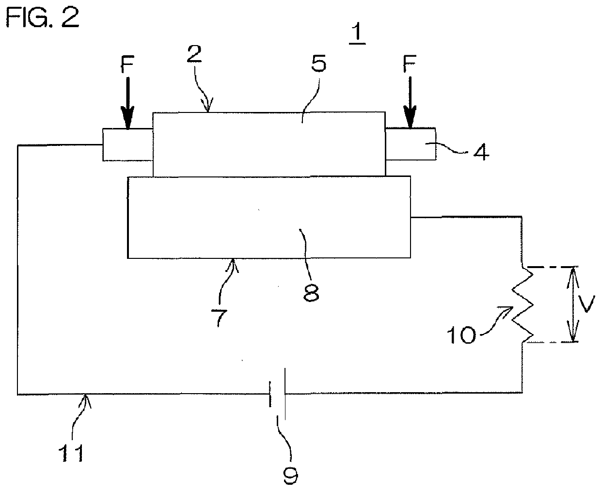
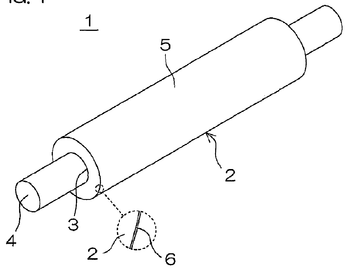
Image

Examples
example 1
Preparation of Rubber Composition
[0179]80 parts by mass of SBR [JSR 1502 by JSR Corporation] and 20 parts by mass of GECO [Epion (registered trademark) ON301 by Daiso Co., Ltd., EO / EP / AGE=73 / 23 / 4 (molar ratio)] were blended as rubber components. The compounding ratio of the SBR with respect to 100 parts by mass of the total quantity of the rubber components was 80 parts by mass.
[0180]A rubber composition was prepared by masticating 100 parts by mass of the total quantity of the rubber components in a Banbury mixer, kneading the mixture while adding components shown in Table 1 except a crosslinking component, and further kneading the mixture while finally adding the crosslinking component.
TABLE 1ComponentPart by MassSulfur-Based Crosslinking Agent0.75Thiourea0.85Accelerator DM0.5Accelerator TS1Accelerator DT0.8Conductive Filler5Acid Acceptor3
[0181]The components shown in Table 1 are as follows:
example 2
[0195]A semiconductive roller was manufactured by preparing a rubber composition similarly to Example 1, except that 70 parts by mass of the SBR, 20 parts by mass of GECO and 10 parts by mass of CR [Shoprene (registered trademark) WRT by Showa Denko K. K.] were blended as rubber components. The compounding ratio of the SBR with respect to 100 parts by mass of the total quantity of the rubber components was 70 parts by mass.
example 3
[0196]A semiconductive roller was manufactured by preparing a rubber composition similarly to Example 2, except that the quantities of the SBR and the CR were changed to 50 parts by mass and 30 parts by mass respectively. The compounding ratio of the SBR with respect to 100 parts by mass of the total quantity of the rubber components was 50 parts by mass.
PUM
 Abstract
Description
Claims
Application Information