Magnetically-Triggered Proximity Switch

a magnet-triggered proximity switch and magnet-triggered technology, applied in the direction of magnetic/electric field switches, magnetic movement switches, electrical equipment, etc., can solve the problems of limiting the application in which the sensor can be used, the inability to use typical sensors in applications, and the inability to reduce the size of proximity switches

Active Publication Date: 2012-08-16
GENERAL EQUIP & MFG COMPANY INC D B A TOPWORX
View PDF2 Cites 11 Cited by
  • Summary
  • Abstract
  • Description
  • Claims
  • Application Information

AI Technical Summary

Benefits of technology

This patent describes how two magnetic components can move back and forth to control the switching of electrical current through a circuit. One component is attached to a movable part that changes its position when another component moves. This allows for smooth transition between different positions without causing any sudden stops or starts. A special design also helps reduce friction during this motion. Overall, this technology makes it possible to create more efficient and reliable systems for controlling electricity.

Problems solved by technology

The technical problem addressed in this patent text is the large size of magnetically-triggered proximity switches, which limits their placement in areas with limited free space. The need for power also limits their use in applications. There is a need for a smaller magnetically-triggered proximity switch that can accommodate high load values and be easily manufactured.

Method used


Image

  • Magnetically-Triggered Proximity Switch
  • Magnetically-Triggered Proximity Switch
  • Magnetically-Triggered Proximity Switch

Examples


Embodiment Construction

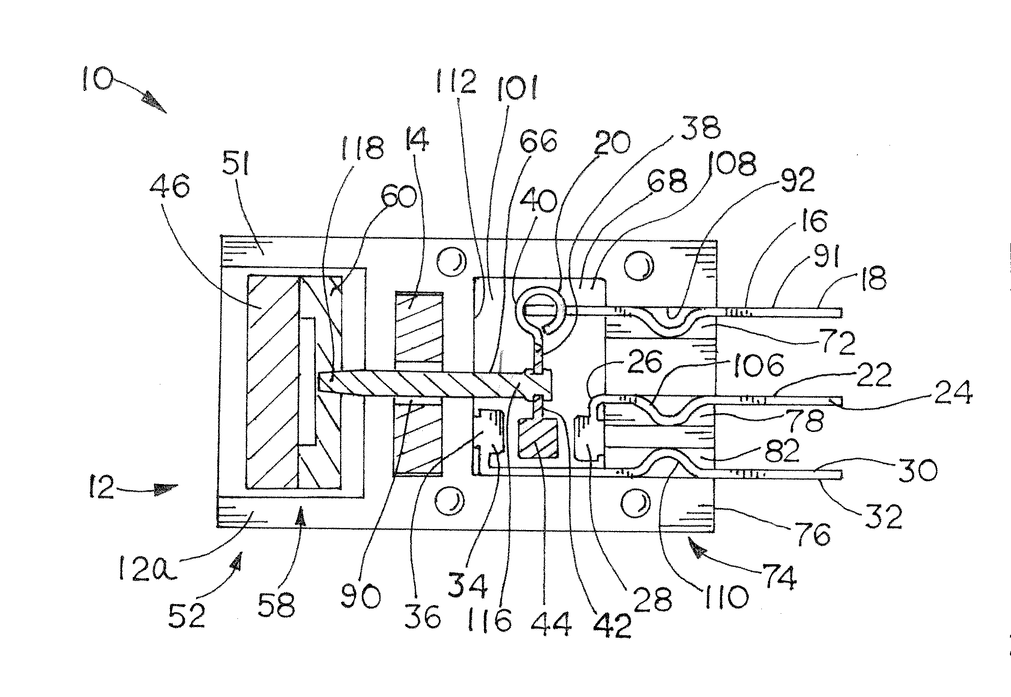
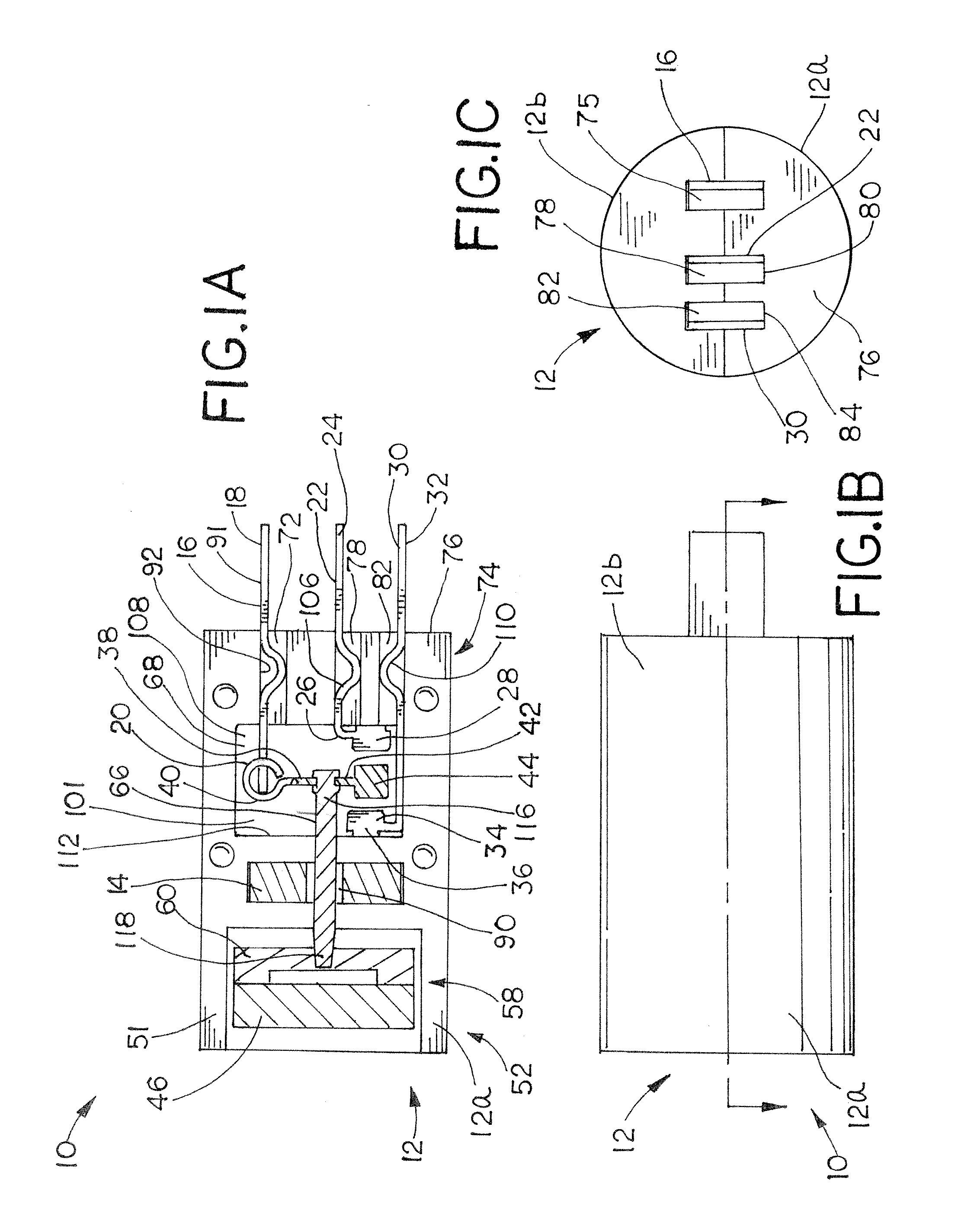
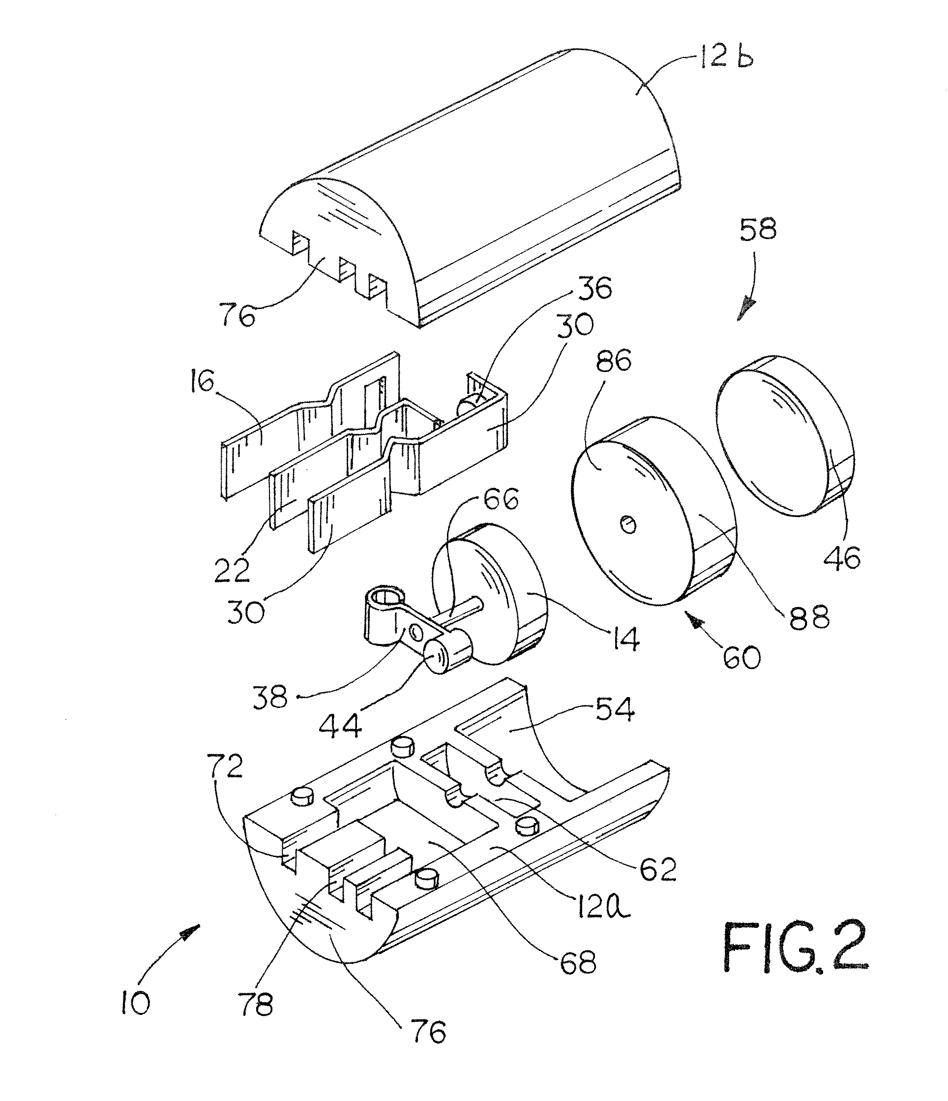
[0033]As illustrated in FIG. 1A, a magnetically-triggered proximity switch 10 includes a switch body 12 and a first magnet 14 non-movably secured within the switch body 12. The proximity switch 10 also includes a common arm 16 having a first end 18 and a second end 20, and the second end 20 of the common arm 16 is disposed within the switch body 12. The proximity switch 10 further includes a primary arm 22 having a first end 24 and a second end 26. The second end 26 is disposed within the switch body 12, and the second end 26 includes a primary contact 28. In addition, the proximity switch includes a secondary arm 30 having a first end 32 and a second end 34. The second end 34 is disposed within the switch body 12, and the second end 34 includes a secondary contact 36. A cross arm 38 is disposed within the switch body 12, and the cross arm 38 has a first end 40 and a second end 42. The first end 40 is coupled to the common arm 16 and the second end 42 includes a common contact 44. A...


PUM


Abstract

A magnetically-triggered proximity switch includes a cylindrical switch body and a bias member non-movably secured within the switch body. The proximity switch also includes first and second normally-closed contacts and first and second normally-open contacts. The proximity switch further includes a spherical contact magnet disposed within the switch body, with the contact magnet being movable relative to the bias member from a first switch position and a second switch position. In the first switch position, an attraction to the bias member maintains the contact magnet in contact with the first and second normally-closed contacts, thereby completing a circuit between the first and second normally-closed contacts. In the second switch position, an attraction to a movable target external to the switch body moves the contact magnet into contact with the first and second normally-open contacts, thereby completing a circuit between the first and second normally-open contacts.

Description


Claims


Application Information

Patent Timeline
Owner GENERAL EQUIP & MFG COMPANY INC D B A TOPWORX
Why Eureka
Try Eureka