Large signal VCO

a technology of resonant circuits and large signals, applied in pulse generators, dc-ac conversion without reversal, pulse techniques, etc., can solve the problems of undesirable load detuning, power transfer principles using resonant circuits, unit resonance frequency detuning,

Active Publication Date: 2012-10-04
REHM MARKUS
View PDF1 Cites 24 Cited by
  • Summary
  • Abstract
  • Description
  • Claims
  • Application Information

AI Technical Summary

Benefits of technology

[0018]FIG. 1 shows a circuit to control the frequency of a large signal network according to a first prior art.
[0019

Problems solved by technology

The general disadvantage of wireless power transfer principles using resonant circuits in the base station and/or in the load unit is the resonance frequency detuning.
This has been due to component tolerances, component aging, variable coupling and load conditions.
This load detuning is undesirable because the impedance of the resonant circuit is frequency selective and a predetermined operating frequency no longer matches the resonant frequency.
In addition the drive waveforms become more distorted and the driver circuits generate more harmonics.
The well-known network measurement method measures while in an interval, the resonant frequency of the network and then it operates at this frequency, but has no ability to control the network frequency actively.
This control met

Method used


Image

  • Large signal VCO
  • Large signal VCO
  • Large signal VCO

Examples


Embodiment Construction

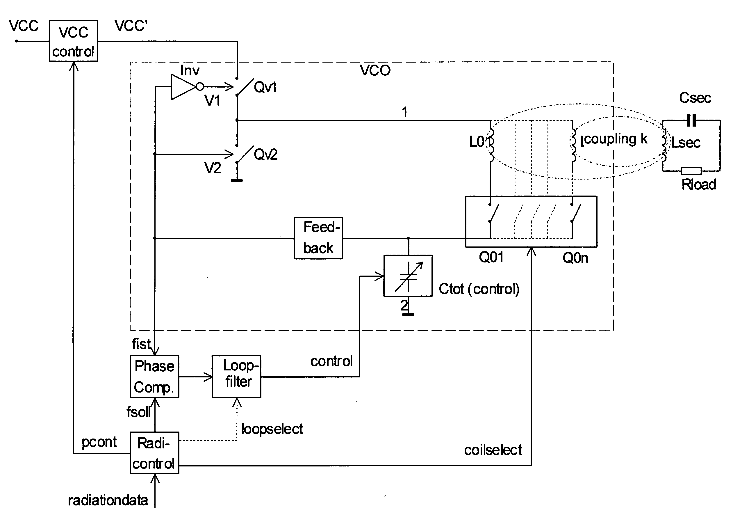
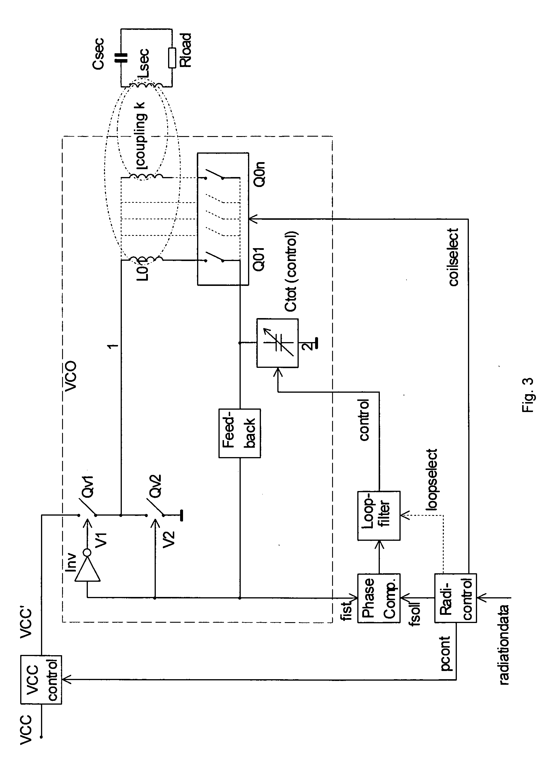
[0034]The block diagram of a series push-pull oscillator with a controlled capacitor in the resonant network shown in FIG. 3 according to a first embodiment. Herein, this oscillator is used as a base station in a wireless power supply system, but it can be used as any oscillator. The switches Qv1 and Qv2 form a series push-pull stage (half bridge), which couples its center alternately either to VCC′ or to a reference potential (ground). The switches Qv1 and Qv2 are alternately open or closed. In one embodiment, the switches Qv1 and Qv2 are of the same channel type (either two P-channel or two N-channel MOSFETs respectively either two PNP or two NPN IGBTs). The opposite-phase drive signals V1 and V2 are guaranteed by the inverter (Inv). In another embodiment, the switches Qv1 and Qv2 are of complementary types (P / N channel MOSFETs or PNP / NPN bipolar transistors or IGBTs), there Inv is not implemented. The center tap of the switches is connected to a series resonant circuit consisting...


PUM


Abstract

An alternation voltage- or current generator comprises a first switch driving output network whose frequency can be tuned. The tuneable network comprises a first Inductor that is coupled with a first capacitor. A second inductor and/or at least a second capacitor and/or at least a series circuit of a third inductor and a third capacitor which is coupled via at a second switch to the network. The second switch is controlled by a controlled delay (PWM) which is synchronized by a sign change of current and/or voltage in the network.

Description

FIELD OF THE INVENTION[0001]The present invention relates to the generation of electromagnetic waves by means of resonant network and more particularly to near field power transmission for RFID and wireless power supplies. Furthermore, the current invention relates to control the resonant frequency of an oscillator by means of a switched resonant network.BACKGROUND OF THE INVENTION[0002]Wireless power supplies can be realized by means of inductive and / or capacitive near-field coupling. This is used in many RFID systems and wireless battery chargers. A source unit, hereinafter referred to as the base station, generates an electromagnetic alternating field whose radiation unit represents a resonant circuit. By means of such a resonant circuit the alternating field is produced efficiently at relatively low cost, because the driver circuits generate virtually no switching losses (ZVS zero voltage or zero current switching ZCS). The filtering effect of the resonant circuit influences the...

Claims


Application Information

Patent Timeline
IPC IPC(8): H03L7/06H03B5/18
CPCH02J17/00H02M3/3387H03B5/1218H03B5/1268H04B5/0037H03J2200/15H02M7/48Y02B70/1433Y02B70/1441H03L7/099H02M2007/4815H02J50/12Y02B70/10H02J50/402H02M7/4815H03B5/08
Inventor REHM, MARKUS
Owner REHM MARKUS
Why Eureka
Try Eureka