Illumination device

a technology of illumination device and led light, which is applied in the field of illumination device, can solve the problems of generating more heat, negative impact on the performance of imaging sensor, and needing to cover the illumination of led lights, so as to reduce the risk of producing an overexposed picture, power consumption and heat generation, and good a picture

Inactive Publication Date: 2012-10-18
AXIS
View PDF12 Cites 10 Cited by
  • Summary
  • Abstract
  • Description
  • Claims
  • Application Information

AI Technical Summary

Benefits of technology

[0021]As a further option, information regarding ambient light intensity may be received, and the plurality of light emitting elements may be controlled such that a total output intensity of the illumination device is lowered if the ambient light intensity exceeds a predetermined level. This makes it possible to even further adapt the illumination provided by the illumination device to the needs of the camera so that as good a picture as possible is obtained. By reducing the output intensity to the level needed in addition to the ambient light, the power consumption and heat generation can be even further reduced. In addition, the risk of producing an overexposed picture is also lowered.

Problems solved by technology

However, a problem when mounting the LEDs on the camera head is that the LEDs will then be closely placed to the imaging sensor, which in turn means that the heat generated by the LEDs can negatively impact the performance of the imaging sensor.
Disturbing reflections when the LEDs are placed close to the camera lens is another problem which may occur when the LEDs are mounted on the camera head.
However, a problem occurring when the LEDs are mounted on the camera base is that the illumination of the LEDs then need to cover all possible viewing angles of the camera head.
Illuminating the whole scene implies that a large number of LEDs is needed and that a large amount of input power is needed to operate the LEDs, this in turn generating more heat.

Method used


Image

  • Illumination device
  • Illumination device
  • Illumination device

Examples


Embodiment Construction

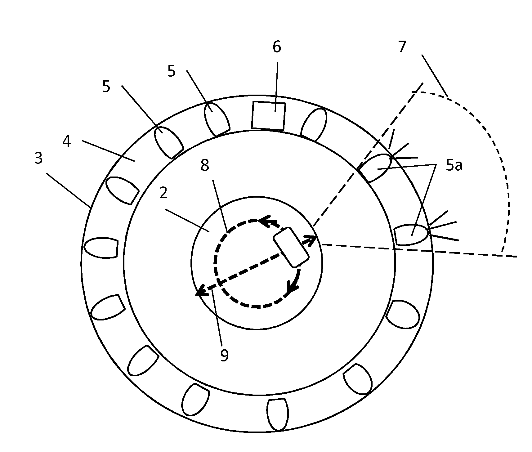
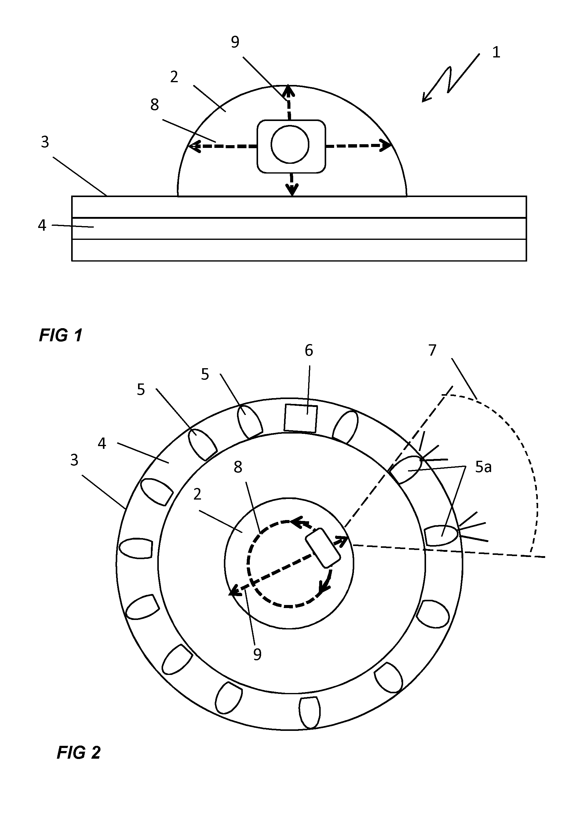
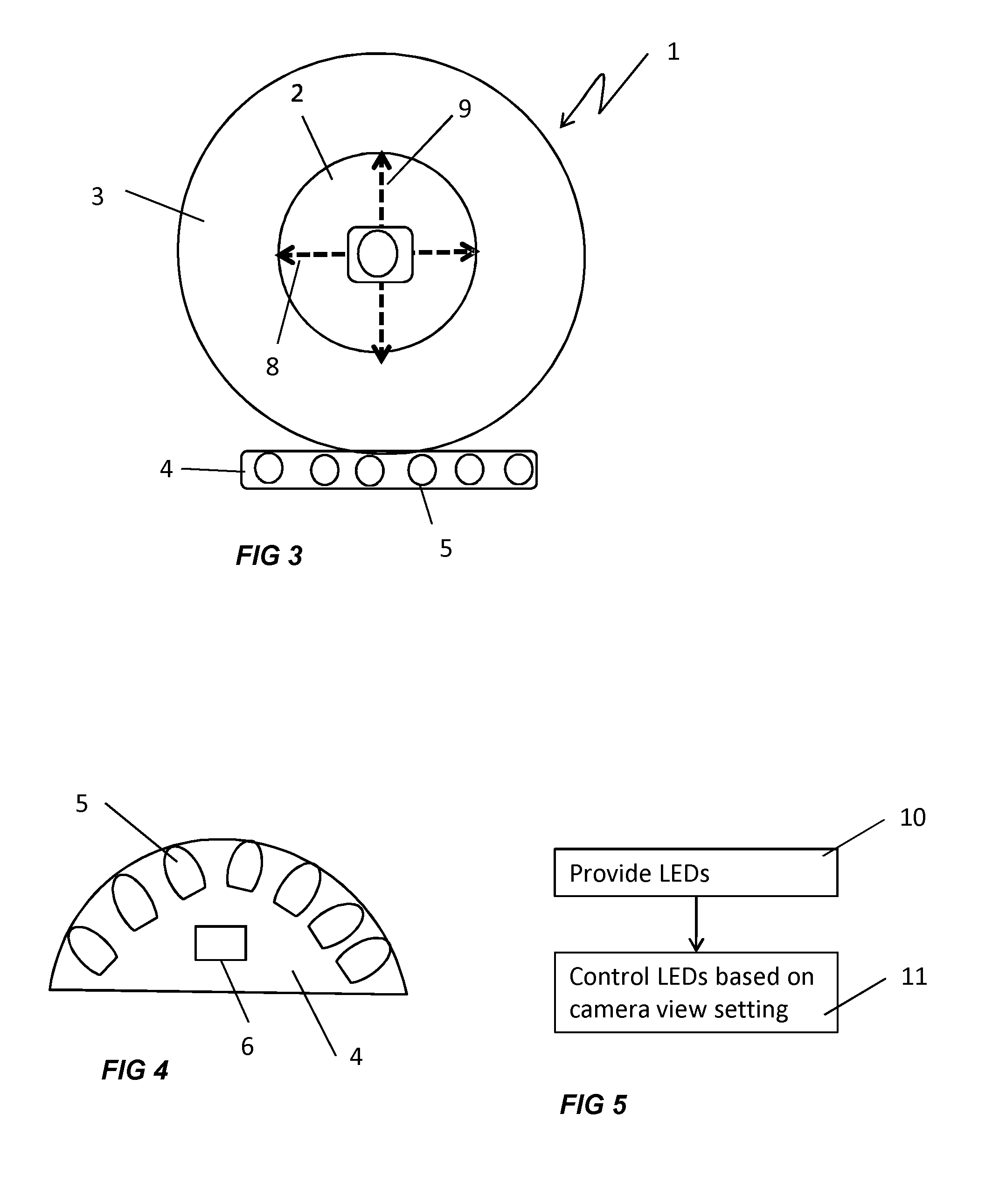
[0028]In FIGS. 1 and 2, a camera 1 having a dome-shaped camera head 2 mounted on a circular camera base 3 is shown. The camera is equipped with an illumination device 4. As shown in FIG. 2, the illumination device 4 comprises a numbers of light emitting elements 5, e.g., in the form of LEDs, mounted on the camera base 3. The light emitting elements 5 may be emitting light in the visible or non-visible spectrum. As one example, they may be designed for emitting in the infra-red or near infra-red spectrum, and it may be noted that both for visible and non-visible radiation, LEDs are just one example of light emitting elements which could be used. Other possible choices include but are not limited to light bulbs, halogen lamps and gas discharge lamps. The light emitting elements 5 are mounted along the circumference of the camera base 3 and surround the camera head 2. The light emitting elements may be mounted in a ring-shape or partial ring shape, in one or more rows, surrounding at l...


PUM


Abstract

An illumination device and method for illuminating a scene monitored by a camera uses a plurality of light emitting elements and an illumination control unit. The illumination control unit is arranged to individually control the output intensity of the plurality of light emitting elements based on a camera view direction setting, such that illumination is provided in a view direction of the camera.

Description

CROSS-RELATED APPLICATIONS[0001]This application claims priority to U.S. Provisional Application No. 61 / 476,057 filed on Apr. 15, 2011 and EPC application 11162211.4 filed on Apr. 13, 2011, which are incorporated by reference as if fully set forth.TECHNICAL FIELD[0002]The present invention relates to an illumination device for illuminating a scene monitored by a camera, and to a method of illuminating a scene monitored by a camera.BACKGROUND ART[0003]Surveillance cameras used to monitor a specific setting may from time to time need additional lighting to be able to give a good picture of the environment that they are used to monitor. This is for instance the case during night time in an outdoor setting when the natural light is insufficient for the camera or in an indoor situation when, e.g. for energy saving purposes, the lights are switched off. Some type of lighting can then be used in combination with the surveillance camera. A common choice is to use light emitting diodes, LEDs...

Claims


Application Information

Patent Timeline
Patent Type & Authority Applications(United States)
IPC IPC(8): G03B15/03
CPCG03B15/03G03B15/0457H04N5/2354H04N5/2256G03B15/05G03B2215/0539H04N23/56H04N23/74
Inventor FRANSSON, KENT
Owner AXIS
Why Eureka
Try Eureka