
Backlight module, display panel comprising same and electronic device

A technology for a backlight module and a light guide plate is applied in the fields of display panels, electronic equipment, and backlight modules, and can solve the problems of cumbersome preparation process, large thickness, and the need for improvement of the backlight module.

Inactive Publication Date: 2017-05-24
BOE TECH GRP CO LTD +1
View PDF5 Cites 4 Cited by
  • Summary
  • Abstract
  • Description
  • Claims
  • Application Information

AI Technical Summary

Problems solved by technology

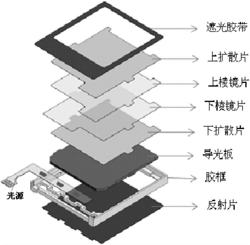
Currently, refer to figure 1 , the backlight module generally includes: a light-shielding tape, an upper diffusion sheet, an upper prism sheet, a lower prism sheet, a lower diffusion sheet, a light guide plate, a plastic frame and a reflection sheet, which includes multiple optical films, with a complex structure and a large thickness. And the preparation process is cumbersome
As the demand for thinner and lighter liquid crystal modules is getting higher and higher, traditional backlight modules are difficult to meet
[0003] Therefore, the current backlight module still needs to be improved

Method used


Image

  • Backlight module, display panel comprising same and electronic device
  • Backlight module, display panel comprising same and electronic device
  • Backlight module, display panel comprising same and electronic device

Examples


Embodiment 1

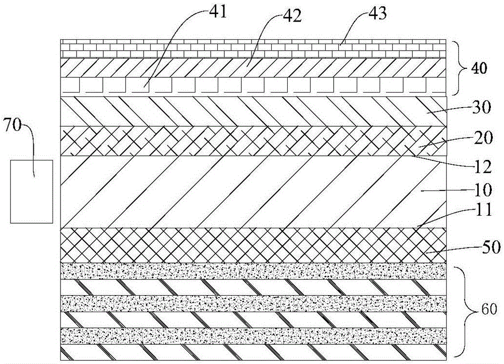
[0052] In this embodiment, a plurality of coating layers are respectively formed on the light-emitting surface and the light-incident surface of the light guide plate (PMMA) by evaporation, coating, etc., to obtain image 3 In the backlight module shown, the refractive index of the light guide plate is 1.49, the refractive index of the first low-refractive coating layer and the second low-refractive coating layer are about 1.38, and the refractive indices of the titanium dioxide layer and the silicon dioxide layer in the Bragg reflective layer are respectively are 2.38 and 1.46, and the quantity and thickness of titanium dioxide layer and silicon dioxide layer are shown in the table below. At the same time, according to the above steps to form a contrast backlight module, the difference is that a single-layer silver coating or aluminum coating is formed on the light-incident surface of the light guide plate instead of a Bragg reflection layer.

[0053]

[0054] Measure the ...


PUM


Abstract

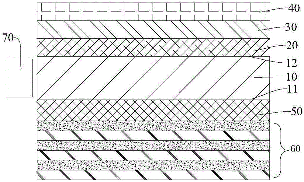
The invention provides a backlight module, a display panel comprising the same and an electronic device. The backlight module comprises a light guide plate, a first low-refractive coating, a diffusion coating, a high-refractive coating, a second low-refractive coating, a Bragg reflective coating and light sources, wherein the light guide plate is provided with a light-exiting surface and a light-entering surface which are opposite to each other, the first low-refractive coating is arranged on the light-exiting surface of the light guide plate, the diffusion coating is arranged on the upper surface of the first low-refractive coating, the high-refractive coating is arranged on the upper surface of the diffusion coating, the second low-refractive coating is arranged on the light-entering surface of the light guide plate, the Bragg reflective coating is arranged on the lower surface of the second low-refractive coating, and the light sources are arranged on side faces of the light guide plate. According to the membrane-free backlight module with a plurality of coatings, the structure of the backlight module is greatly simplified, yield is improved, light loss is reduced, brightness is greatly improved, the thickness of the whole backlight module is only equal to that of the upper and lower coatings of the light guide plate, the backlight module can be ultra-thin, and pictures and quality of the display panel comprising the backlight module are improved.

Description

technical field [0001] The invention relates to the field of display technology, in particular, to a backlight module, a display panel and electronic equipment containing the same. Background technique [0002] The backlight module is one of the key components of the LCD panel. The function is to supply sufficient brightness and evenly distributed light source so that it can display images normally. Currently, refer to figure 1 , the backlight module generally includes: a light-shielding tape, an upper diffusion sheet, an upper prism sheet, a lower prism sheet, a lower diffusion sheet, a light guide plate, a plastic frame and a reflection sheet, which includes multiple optical films, with a complex structure and a large thickness. And the preparation process is loaded down with trivial details. As the demand for thinner and lighter liquid crystal modules is getting higher and higher, traditional backlight modules are difficult to meet. [0003] Therefore, the current bac...

Claims


Application Information

Patent Timeline
IPC IPC(8): G02F1/13357G02B6/00
CPCG02F1/133615G02B6/0051G02B6/0055G02F2201/34G02B6/009G02B6/0053G02B6/0036G02B6/0043G02B6/0065G02F1/133606G02F2201/307
Inventor 王雪绒张财政马俊杰王佳男尹清平禹璐
Owner BOE TECH GRP CO LTD
Learn More