Image apparatus

a technology of image apparatus and general display device, which is applied in the field of image apparatus, can solve the problems of not being able to evaluate the degree of focus through the display device, the operator cannot see the entire image, and the general display device in the image apparatus is small, and achieves the effect of substantial difference in display timing

Inactive Publication Date: 2012-10-25
RICOH KK
View PDF10 Cites 66 Cited by
  • Summary
  • Abstract
  • Description
  • Claims
  • Application Information

AI Technical Summary

Benefits of technology

[0016]According to an embodiment of the present invention, a first image that is an enlarged part of the entirety to be photographed and a second image of the entirety are displayed in the same display without a substantial difference in the display timing or with only a small difference in the display timing. The operator can thereby confirm the degree of focus and the entirety of the photograph before taking a picture.
[0017]Further,

Problems solved by technology

However, the screen of the general display device in the image apparatus is small and has a low resolution, and just shows the image in a decreased size and decreased number of pixels.
In other words, the operator may not be able to evaluate the degree of focus through the display device.
However, the operator can not see the entirety of the image since the screen just shows the part of the image.
The operator can not recognize a whole area to be photographed.
The operator may miss the object when the object moves fast.
Further, if the object is affected by changes around the object, the operator may miss a timing

Method used


Image

  • Image apparatus
  • Image apparatus
  • Image apparatus

Examples


first embodiment

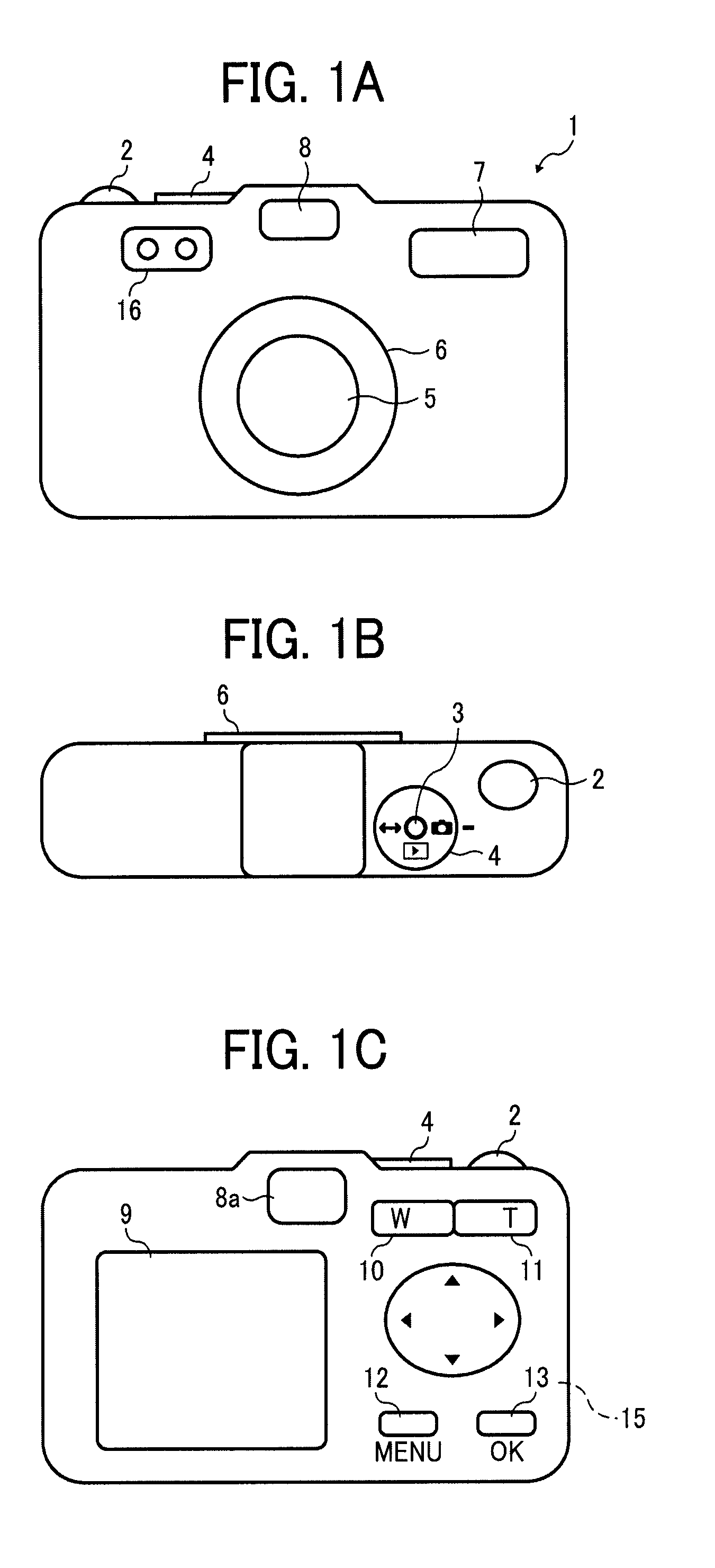
[0034]FIGS. 1A to 1C are diagrams illustrating the outward appearance of a digital still camera 1 (hereinafter digital camera 1) according to the FIG. 1A is a front view illustrating the digital still camera, FIG. 1B is a top view illustrating the digital still camera, and FIG. 1C is a rear view illustrating the digital still camera.

[0035]As shown in FIG. 1B, the digital still camera according to this embodiment includes on the top surface thereon a release shutter 2, a power switch 3, and a mode dial 4 that is operated to switch between a recording mode and reproduction mode. As shown in FIG. 1A, the digital still camera includes on the front surface thereon a lens barrel unit 6 including a main optical system 5, a flash light emitting unit 7, an optical finder 8, and a sub optical system 16. As shown in FIG. 1C, the digital still camera according to this embodiment includes on the rear surface thereof a liquid crystal display (LCD) monitor 9, an optical finder (rear surface) 8a, ...

second embodiment

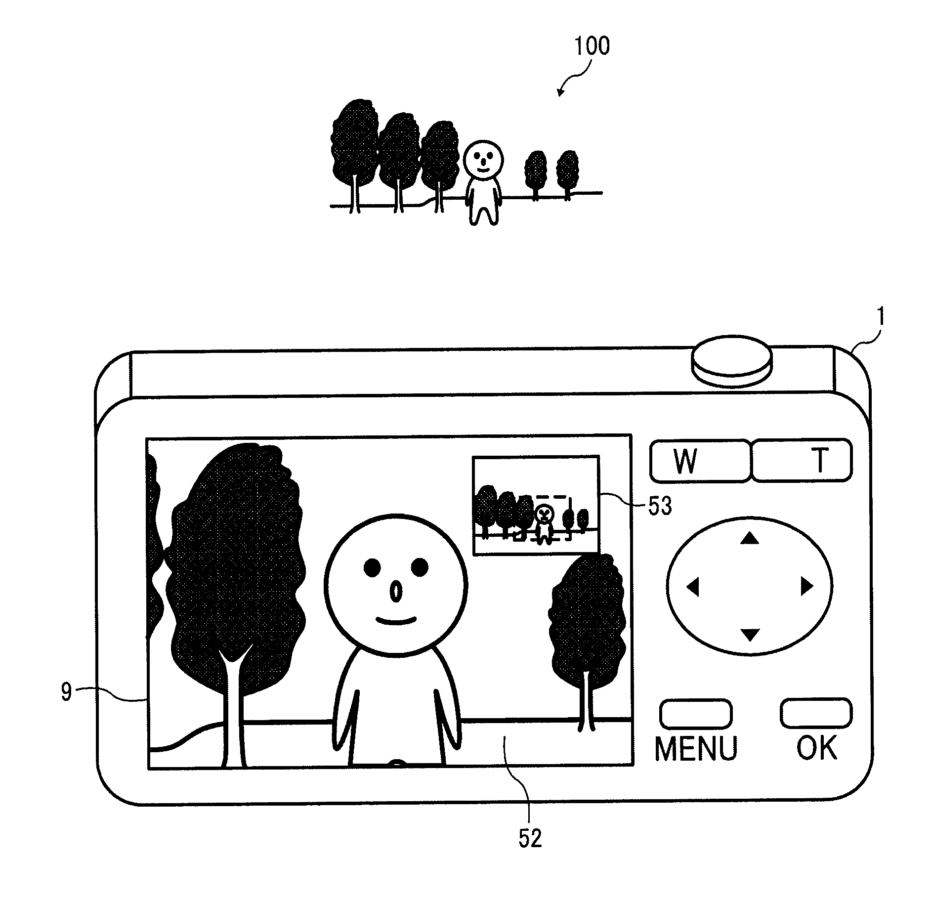
[0112]A second embodiment discloses a live view image on the LCD 9 in a case of executing the zoom operation of the digital camera 1.

[0113]FIG. 9 is a diagram illustrating the live view image on the LCD 9 in a case of executing the zoom operation. The LCD 9 of the digital camera 1 displays the zoomed image 52 on the entire screen, and it displays the surrounding image 53 with the zoomed image 52. The zoomed image 52 is an image of the object 100 which is zoomed on by the main optical system 5. The surrounding image 53 is an image surrounding the zoomed image 52 by the sub optical system 16.

[0114]In the surrounding image 53, the frame border (dashed line) shows the portion corresponding to the displayed zoomed image 52. The setting of the display as described is referred to as a zoom assistance setting. The display based on the zoom assistance setting is referred to as a zoom assistance view.

[0115]The zoomed image 52 might be displayed over the surrounding image 53 alternatively. The...

third embodiment

[0129]A third embodiment describes the live view image of the digital camera 1 when it includes plural sub optical systems that each have a different focal length.

[0130]Hereinafter, the digital camera 1 includes two sub optical systems that have different focal length from each other. FIG. 12 is an example of the flowchart illustrating the process to select one of the live view images engaged in the zoom position of the main optical system 5.

[0131]The sub optical system having a longer focal length is referred to as H1 and the sub optical system having a shorter focal length is referred to as H2 in the two sub optical systems 16. The angle of view of H2 is wider than that of H1. Therefore, one of the images from the sub optical systems is selected for the zoom assistance view according to the angle of view of the zoomed image 52 captured by the main optical system 5. The angle of view of one of the images selected above is wider but not too much wider than that of the zoomed image 5...


PUM


Abstract

An image apparatus, including a main optical system that captures a first image, a sub optical system that captures a second image to assist capturing the first image, a display device that displays the first image and the second image in a live view, and a signal processor that controls at least one of a frame rate of the first image from the main optical system and a frame rate of the second image from the sub optical system. The signal processor controls the frame rate of the first image data and the second image data such that the first and second frame rates become the same, and the display device displays the first image and the second image on the display device.

Description

CROSS-REFERENCE TO RELATED APPLICATIONS[0001]The present application claims priority to and incorporates by reference the entire contents of Japanese Patent Application No. 2011-095398 filed in Japan on Apr. 21, 2011.BACKGROUND OF THE INVENTION[0002]1. Field of the Invention[0003]The present invention relates to an image apparatus, for example a digital still camera. In particular, it relates to a displaying technology in operations of a manual focus mode and a zoom mode.[0004]2. Description of the Related Art[0005]Conventionally, an image apparatus such as a digital still camera includes a small LCD (Liquid Crystal Display) as a display device. The display device displays an image to be captured in real-time. In a case of operating in a manual focus mode, the operator confirms the image on the display device and carries out a release operation for photographing when the object is in focus.[0006]However, the screen of the general display device in the image apparatus is small and ha...

Claims


Application Information

Patent Timeline
IPC IPC(8): H04N5/262H04N5/225
CPCH04N5/23212H04N5/2258H04N5/23296H04N5/23293H04N23/45H04N23/673H04N23/632H04N23/635H04N23/69
Inventor KAZAMA, YASUHIRO
Owner RICOH KK
Why Eureka
Try Eureka