Focused Plenoptic Camera Employing Different Apertures or Filtering at Different Microlenses

a technology of microlenses and apertures, applied in the field of focused plenoptic cameras, can solve the problems of difficult environment capture, conventional cameras fail to capture a large amount of optical information, and the image contains no information about the direction of light, etc., to achieve sharper, higher spatial resolution, and increase or maximize spatial resolution

Active Publication Date: 2012-11-08
ADOBE SYST INC
View PDF4 Cites 92 Cited by
  • Summary
  • Abstract
  • Description
  • Claims
  • Application Information

AI Technical Summary

Benefits of technology

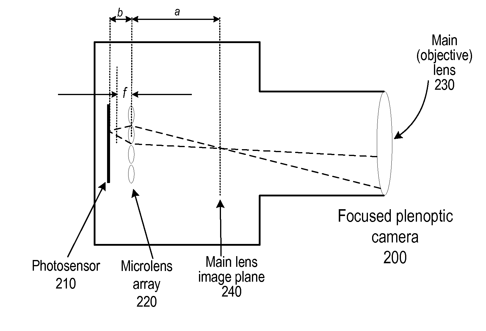
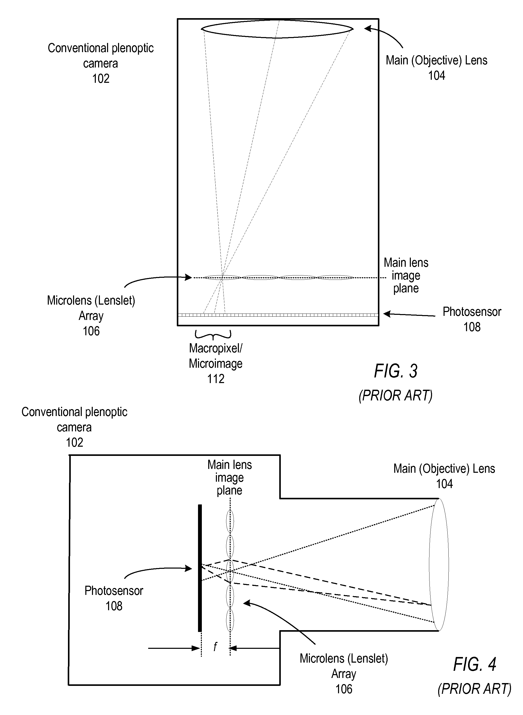
[0013]Various embodiments of methods and apparatus for capturing and rendering images with focused plenoptic cameras employing different filtering at different microlenses are described. In a focused plenoptic camera, the main camera lens creates an image of a scene in front of the camera at the focal plane of the main lens. That image is re-imaged onto the sensor multiple times by an array of microlenses. The microlenses are focused on the image of the scene created by the main lens at the focal plane, instead of being focused on the main lens itself as in conventional plenoptic cameras. This serves to increase or maximize spatial resolution, and thus the focused plenoptic camera achieves sharper, higher spatial resolution microlens images than those produced by conventional plenoptic cameras.
[0014]In a focused plenoptic camera, if the scene is sufficiently far from the camera, the scene may be considered to be at infinity. The main camera lens creates an image of the scene at the focal plane of the main lens. Different ones of the microlenses may project identical or nearly identical microimages of the image at the focal plane onto the sensor. Thus, each point of the image at the focal plane is re-imaged onto the sensor multiple times by multiple microlenses in the microlens array of a focused plenoptic camera. Embodiments may leverage these characteristics of the focused plenoptic camera by applying different optical elements, such as different filters or different apertures, at different ones of the microlenses to capture various characteristics of light, such as luminance, color, polarization, and so on, differently (e.g., at different levels of exposure for luminance, at different wavelengths of color, at different angles of polarization, etc.) in different microimages. All of the microimages are captured at the same time in a single image (referred to as a flat) at the sensor. Thus, multiple microimages of the same image of a scene may be captured at different colors, different exposures, different polarities, etc., in a single image at the same time with a focused plenoptic camera according to embodiments. Images captured using embodiments of a focused plenoptic camera with different lenses may be used in High Dynamic Range (HDR) imaging, spectral imaging, and other imaging applications. When the main image created by the main lens of the focused plenoptic camera represents objects from a scene that are at optical infinity, those objects are exactly at the focal plane of the camera, one focal length from the main lens. The different views of the main image captured by the different microlenses are identical or nearly identical 3D views of the objects, that is identical or nearly identical images, but modified in brightness, color, polarization, or other characteristics. Thus, imaging functions, such as HDR imaging and spectral imaging, performed according to embodiments may produce precise and high quality output images, such as HDR images, color images, and so on.
[0019]In embodiments employing color filters, different color filters may be employed at different microlenses to thus capture microimages specific to different wavelengths of light corresponding to the respective color filters. The microimages from the raw flat may be appropriately assembled to generate two or more images of the captured scene each corresponding to one of the color filters. Two or more of the images thus generated may be combined to generate color output images of the scene. A focused plenoptic camera using an appropriate pattern of different color filters applied to the microlenses in the array may capture two, three, four, or even more microimages that include the same point in the image in different color channels. Embodiments of a focused plenoptic camera, using a pattern of 100 different color filters at the microlenses may, for example, sample 100 wavelengths of light at each point in an image. Thus, embodiments of a focused plenoptic camera using color filters may provide true spectral imaging.

Problems solved by technology

However, this 2-D image contains no information about the direction of the light that strikes the photosensor.
Thus, conventional cameras fail to capture a large amount of optical information.
Such environments are difficult to capture, for example, in 8-bit images, which provide a pixel brightness range of only 0 to 255, or even in 10- or 12-bit images as captured by most conventional digital cameras.
However, conventional film scanning techniques are generally limited to less than 16-bit (for example, 10-bit or 12-bit); thus, digitizing conventional film limits the dynamic range.
An obvious problem with these conventional methods is that it is difficult to generate HDR images of action scenes, where one or more objects in the scene are moving or changing, as two different images of the scene captured at different times would be quite different in content.
Multiple synchronized cameras may be used to capture different images of the scene at different exposures; however, this is expensive and difficult to set up properly.

Method used


Image

  • Focused Plenoptic Camera Employing Different Apertures or Filtering at Different Microlenses
  • Focused Plenoptic Camera Employing Different Apertures or Filtering at Different Microlenses
  • Focused Plenoptic Camera Employing Different Apertures or Filtering at Different Microlenses

Examples


example results

[0127]Some embodiments of a focused plenoptic camera as described herein may be implemented in film cameras. Embodiments may, for example, be implemented in large-format film cameras. An example large-format film camera embodiment is illustrated in FIG. 8. One example embodiment may, for example, be implemented in large-format film camera using a 135 mm objective lens and 4×5 format film. A focused plenoptic camera based on a large-format film camera rather than on a digital camera may be used for experimental purposes in order to avoid resolution constraint of digital sensors. However, film camera embodiments of the focused plenoptic camera design are practical and may have practical applications. In conjunction with current high-resolution scanners used to digitize captured images from negatives or prints, large-format film camera embodiments are capable of 1 gigapixel, or even higher, resolution for the flat (2D) representation of the 4D radiance (the raw flat).

[0128]A component ...


PUM


Abstract

Methods and apparatus for capturing and rendering images with focused plenoptic cameras employing different filtering at different microlenses. In a focused plenoptic camera, the main lens creates an image at the focal plane. That image is re-imaged on the sensor multiple times by an array of microlenses. Different filters that provide different levels and / or types of filtering may be combined with different ones of the microlenses. A flat captured with the camera includes multiple microimages captured according to the different filters. Multiple images may be assembled from the microimages, with each image assembled from microimages captured using a different filter. A final image may be generated by appropriately combining the images assembled from the microimages. Alternatively, a final image, or multiple images, may be assembled from the microimages by first combining the microimages and then assembling the combined microimages to produce one or more output images.

Description

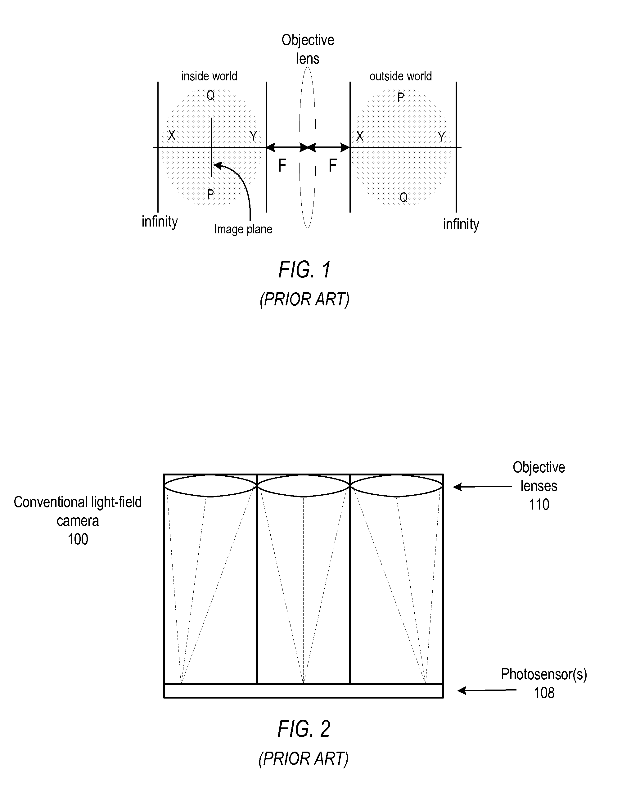
[0001]This application is a continuation of U.S. application Ser. No. 12 / 503,803, filed Jul. 15, 2009, which is incorporated by reference herein in its entirety.BACKGROUNDDescription of the Related Art[0002]In a conventional camera, the main lens maps the 3D world of the scene outside camera into a 3D world inside camera. FIG. 1 illustrates imaging in a conventional camera. “Inside world” represents inside the camera. The shaded oval regions represent the order of depths in the outside world, and the corresponding depths inside the camera. One particular image plane inside the camera is shown. The mapping of the 3D world of the scene outside camera into a 3D world inside camera is governed by the lens equation:1A+1B=1Fwhere A and B are respectively the distances from the lens to the object plane and from the lens to the image plane. This equation is normally used to describe the effect of a single image mapping between two fixed planes. In reality, however, the lens equation describ...

Claims


Application Information

Patent Timeline
Patent Type & Authority Applications(United States)
IPC IPC(8): H04N13/02
CPCG02B3/005G03B11/00G03B17/00H04N9/045H04N5/23229H04N5/2355G03B35/10H04N23/80H04N23/741H04N23/84
Inventor GEORGIEV, TODOR G.LUMSDAINE, ANDREW
Owner ADOBE SYST INC
Why Eureka
Try Eureka