Device for Measuring the Speed of Products in Movement, in Particular Metal Rolled Products in a Rolling Line, and Relative Method

a technology of oblong products and relative methods, which is applied in the direction of average speed measurement, devices using time traversed, devices using optical means, etc., can solve the problems of reduced measurement accuracy, unsuitable and/or ineffectiveness, and high cost and complexity, and achieves high reliability detection, facilitates orientation, and facilitates correct training of sensors

Active Publication Date: 2012-11-29
DANIELI AUTOMATION SPA
View PDF1 Cites 10 Cited by
  • Summary
  • Abstract
  • Description
  • Claims
  • Application Information

AI Technical Summary

Benefits of technology

[0046]A further advantage of the invention is that it allows to measure the rolled metal product without contact, thus overcoming the problems of the state of the art.
[0047]In some forms of embodiment, the device also comprises a coherent light emitter, such as a laser beam, which projects a thin line of light in correspondence with the ideal position in which the axis of sliding of the product whose speed is to be measured must be. In some difficult situations, this serves to facilitate the correct training of the sensors on the product, which guarantees a highly reliable detection.
[0048]In some forms of embodiment, the device according to the present invention comprises a strong container, made of aluminum or other suitable material, metal or non-metal, in which the radiation sensors can be housed, which is supported by a support which allows to attach it and facilitates orientation on both the horizontal and vertical planes.
[0049]In some forms of embodiment, the container is provided with an incorporated circuit for fluid cooling. Depending on the environmental working conditions, the circuit can be fed with water or other cooling fluids.
[0050]In some forms of embodiment, the container provides one or more apertures, typically on the front side, through which the two internal sensors which define the optical windows can observe the moving product.
[0051]Other advantages of the invention are the high precision, with deviations of less than 0.2%, simple use, limited sizes, robust construction, suitable for installation in difficult industrial environments.

Problems solved by technology

Various solutions have been proposed for this purpose, but these have often proved, for various reasons, unsuitable and / or not completely effective.
In particular, methods involving contact are known, for example based on measuring rolls, which are unadvisable given the high temperatures of the rolled metal products in the rolling line, giving rise to problems of slipping, cooling and wear which lead to a reduction in the accuracy of the measurements.
Doppler effect laser measurers are also known, and therefore without contact, but these are costly and complex and, for low or negative speeds, need expensive acoustic-optical modulators.
Moreover, these laser measurers are not suitable for applications dedicated to small section rolled products, which are subject to vibrations or oscillations transverse to the direction of feed, with displacements with respect to the direction of feed of an entity comparable to or greater than the section size of the rolled product itself.
Indeed, in such cases, the use of laser, which produces a substantially dot-like beam of coherent light which hits the rolled product, does not guarantee, in the event of oscillations as above, that the measuring device is constantly trained, which leads to inaccuracies or failure in the measurement of speed.
Furthermore, in the case of small diameter round rolled products of the ribbed type, suitable for structural applications in making reinforced concrete structures, neither the solution with the contact measuring roll nor the Doppler effect laser measurer provide acceptable results, because of the particular structure of the surface of the rolled product.

Method used


Image

  • Device for Measuring the Speed of Products in Movement, in Particular Metal Rolled Products in a Rolling Line, and Relative Method
  • Device for Measuring the Speed of Products in Movement, in Particular Metal Rolled Products in a Rolling Line, and Relative Method
  • Device for Measuring the Speed of Products in Movement, in Particular Metal Rolled Products in a Rolling Line, and Relative Method

Examples


Embodiment Construction

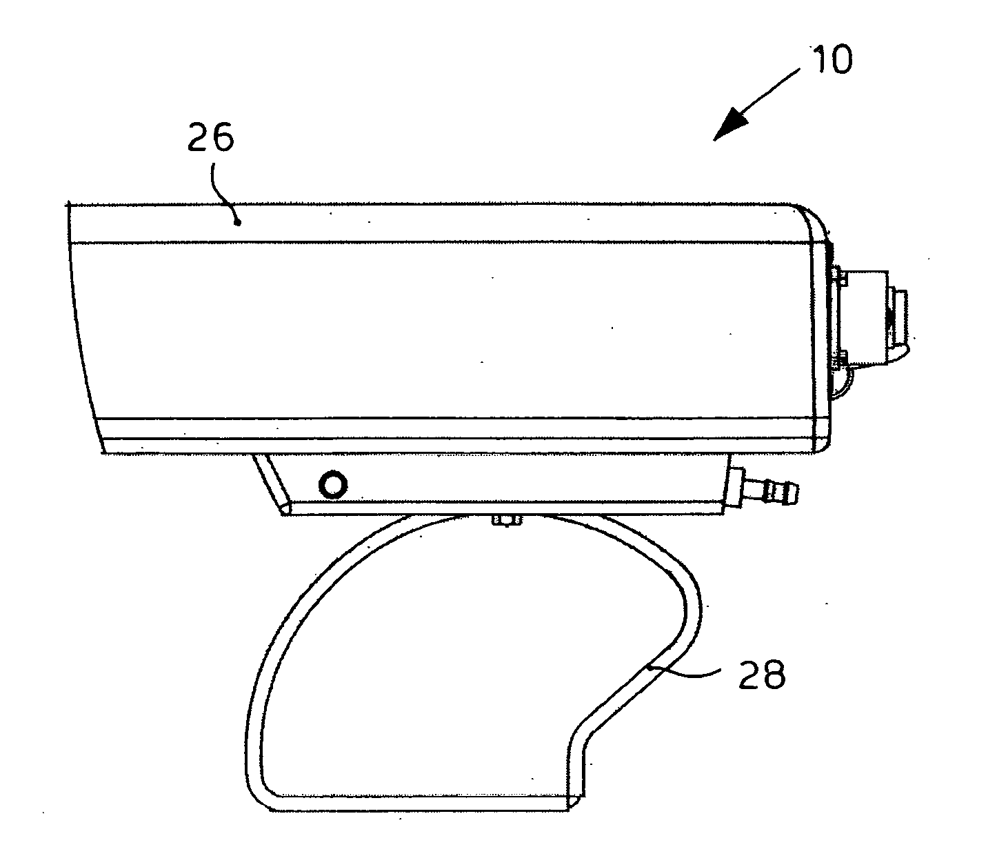
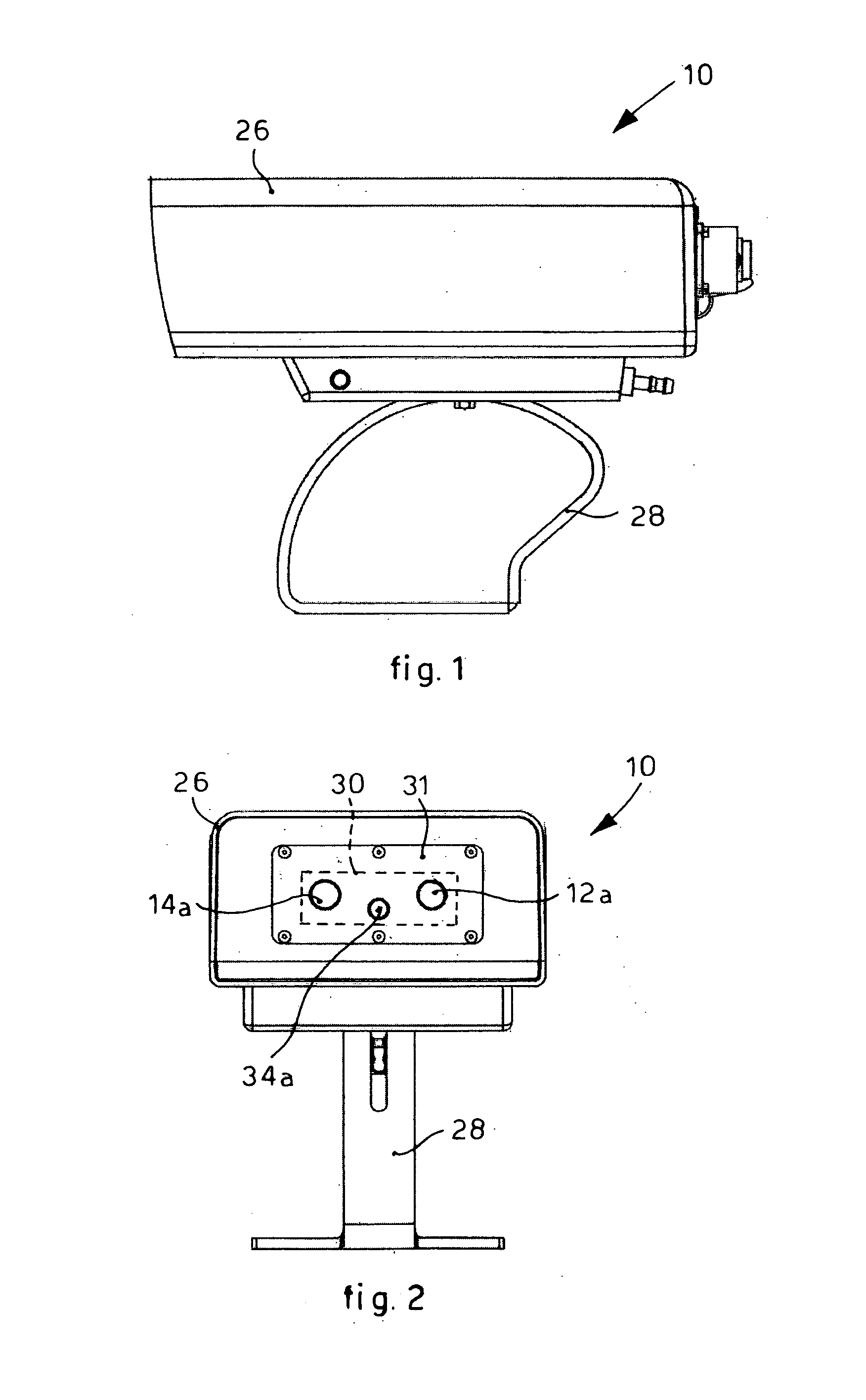
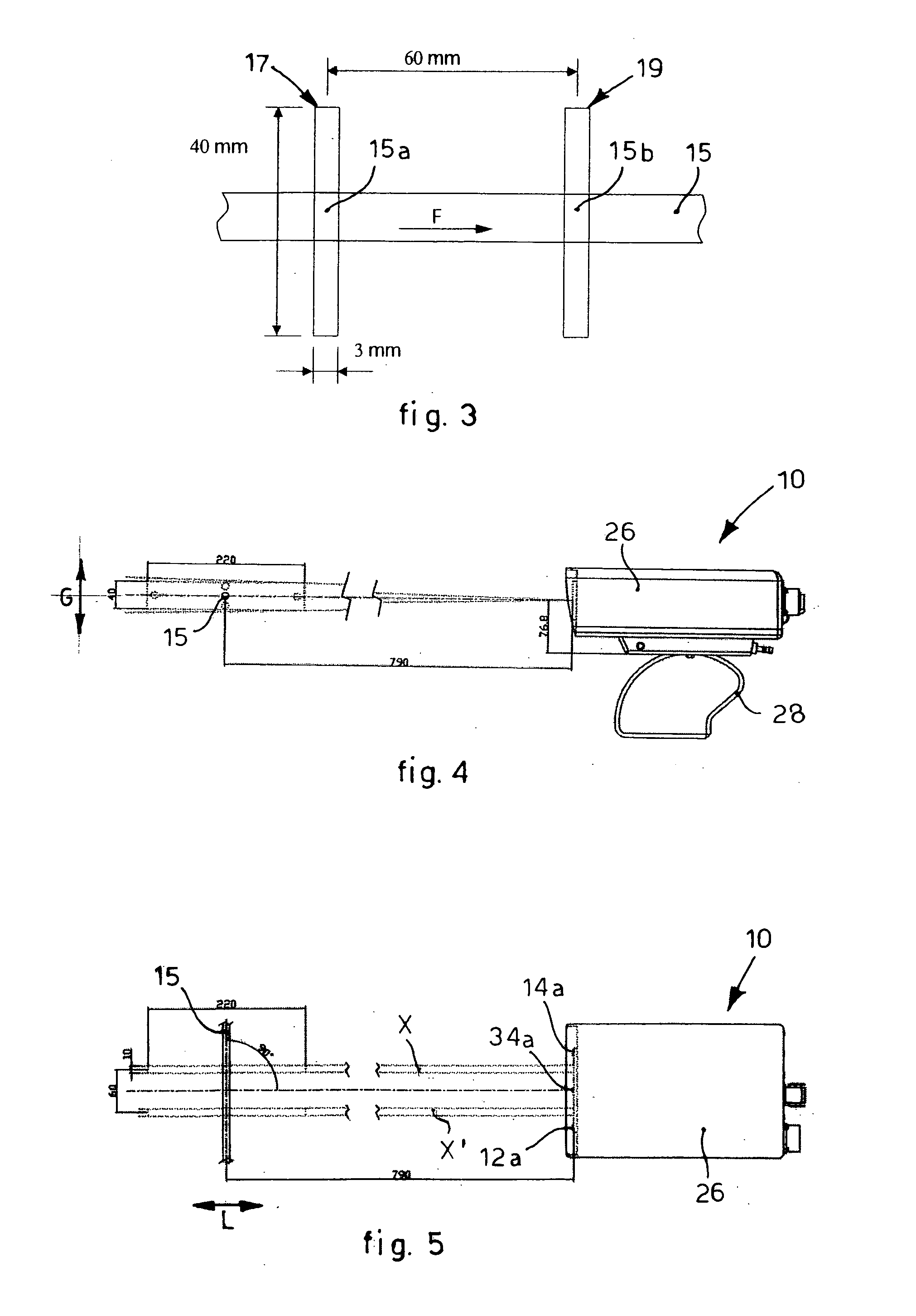
[0076]FIGS. 1 and 2 show a measuring device 10 for measuring the speed of oblong rolled products 15, for example a bar 15, moving along a hot rolling line. However, it should be remembered that the reference number 15 should not be understood as restrictive for the type of oblong product whose speed is to be measured. Indeed, the same measuring device 10 can be used, with the same purposes, for other oblong products moving and emitting radiations, advantageously infrared, without departing from the field of the present invention.

[0077]The measuring device 10 comprises optical units 13 (FIGS. 6, 7, 8, 9, 10, 11, 12a, 12b, 12c) associated with sensors, in this case two 12 and 14 (FIG. 11), which provide photodiodes, in this case sensitive to infrared wavelengths.

[0078]In some forms of embodiment, each optical unit 13 comprises a containing body 35, for example cylindrical, (FIGS. 11, 12a, 12b, 12c) inside which one of the sensors 12, 14 is housed, and a suitable lens 44 (FIGS. 9, 10, ...


PUM


Abstract

Device for measuring speed of oblong products moving along feed direction and emitting radiations, in particular rolled metal products in rolling line, including two radiation sensors, disposed reciprocally at close distance respectively defining an optical observation window, at pre-arranged distance from each other. Each window covers the image of an advancing product determinate portion equal to relative window width, irrespective of portion's movements transverse to feed direction. Sensors observe the presented product portion, on each occasion, in correspondence with associated windows consecutively along feed direction, and measure continuously intensity of radiation from the product portion in correspondence with the windows. Electronic processing unit determines, by processing electric signals associated with detected radiation intensity and arriving from sensors, using algorithms based on the correlation principle, time taken by the product portion to transit from first window to second, successive window, and then, based on distance between windows, calculates product speed.

Description

FIELD OF THE INVENTION[0001]The present invention concerns a device and the relative method for measuring the speed of oblong products in movement, in particular although not exclusively for measuring the speed of rolled metal products, flat or long, in a rolling line, for example in an interstand segment or at exit from a finishing train.BACKGROUND OF THE INVENTION[0002]Within a rolling process for flat or long products, the need to measure the speed of the product at exit from a rolling stand is known.[0003]Various solutions have been proposed for this purpose, but these have often proved, for various reasons, unsuitable and / or not completely effective.[0004]In particular, methods involving contact are known, for example based on measuring rolls, which are unadvisable given the high temperatures of the rolled metal products in the rolling line, giving rise to problems of slipping, cooling and wear which lead to a reduction in the accuracy of the measurements.[0005]Doppler effect l...

Claims


Application Information

Patent Timeline
Patent Type & Authority Applications(United States)
IPC IPC(8): G01P3/36G06F15/00
CPCG01P1/026G01P3/806G01P3/68
Inventor DELLA VEDOVA, FERRUCCIO
Owner DANIELI AUTOMATION SPA
Why Eureka
Try Eureka