Touch cell structure of a touch panel and the touch panel using the same

Active Publication Date: 2012-12-20
G2TOUCH CO LTD
View PDF8 Cites 60 Cited by
  • Summary
  • Abstract
  • Description
  • Claims
  • Application Information

AI Technical Summary

Benefits of technology

[0047]A touch cell structure and a touch panel using the same according to the present invention, includes a conductive pad that forms an electrostatic capacitance with respect to a finger of a human body or the touch unit having a conductive characteristic similar to the finger, and a three-terminal type switching device whose gate terminal is connected with the conductive pad, that is, the touch cell structure is configured into a P2G (Pad to Gate) mode in which the gate terminal of the three-terminal type switching device is connected with the conductive pad. Accordingly, an electrostatic capacitance Ct formed between the touch unit and the conductive pad determines an electric potential of the gate terminal of the switching device, and the output signal of the switching device has tens of times or tens of thousands of times a difference depending upon whether or not a touch input exists. Thus, detection sensitivity and detection accuracy with respect to the touch input

Problems solved by technology

The resistive-type touch input devices or touch panels, however, have low transmittance and undergo the pressure applied to respective substrates, to thereby cause problems that inevitable loss of durability occurs over lapse of use time, it is difficult to accurately perceive touch points, and detection errors occur frequently due to surrounding environments such as temperature and the noise.
However, the electrostatic capacitive-type touch panel needs an expensive detector in order to detect a magnitude of minute electric current, and further needs an analog-to-digital (ADC) converter for converting detected analog electric current to digital electric current, to accordingly cause an inevitable price increase.
In addition, there may raise a problem that a response t

Method used


Image

  • Touch cell structure of a touch panel and the touch panel using the same
  • Touch cell structure of a touch panel and the touch panel using the same
  • Touch cell structure of a touch panel and the touch panel using the same

Examples


Example

BEST MODE

[0068]Hereinbelow, a touch cell structure and a touch panel using the same according to preferred embodiments of the present invention will be described with reference to the accompanying drawings.

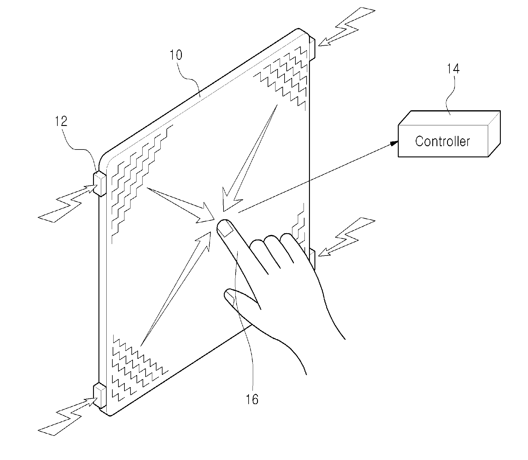
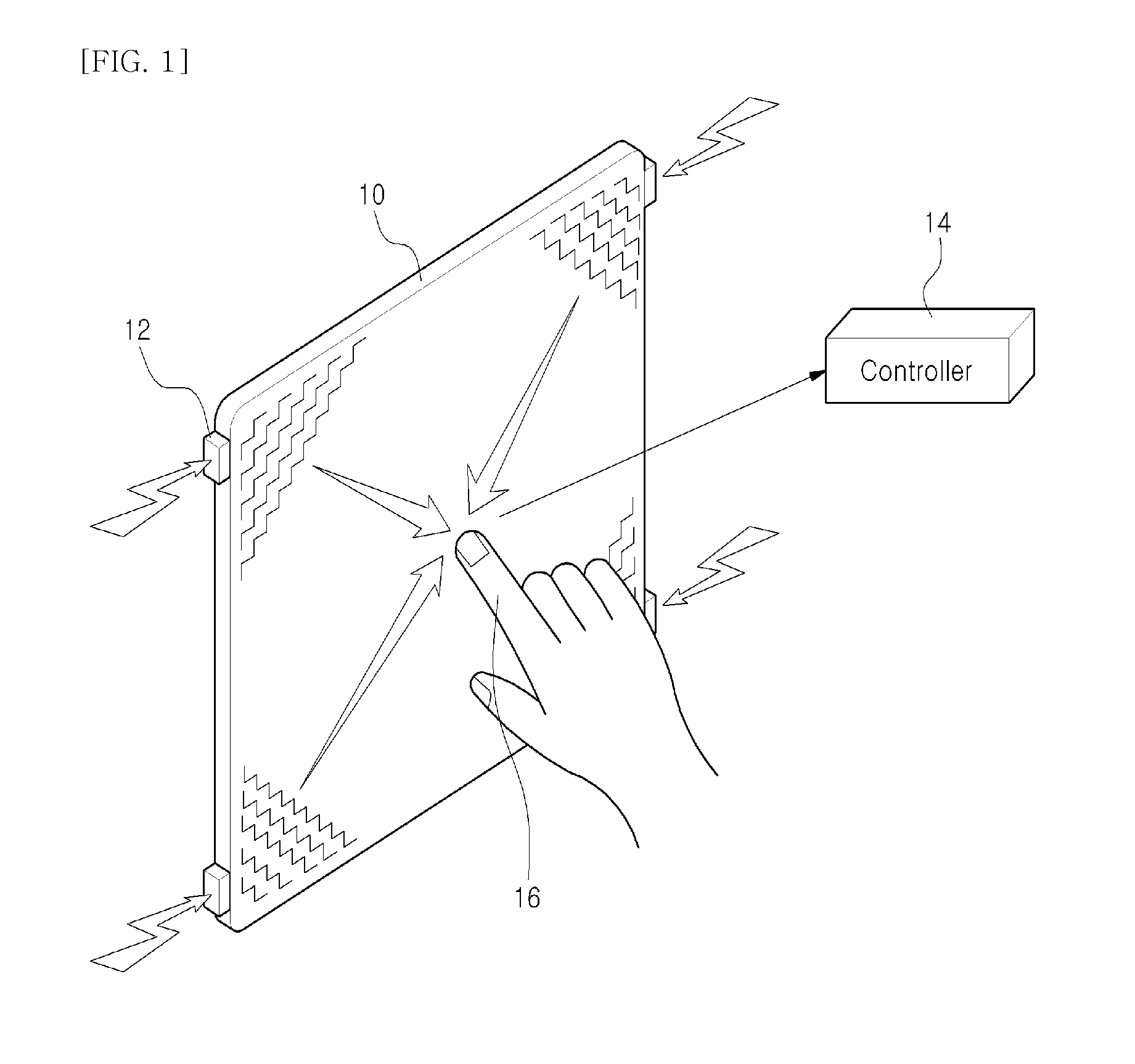
[0069]First, the present invention relates to a touch cell structure for a touch panel that is added on an upper surface of a display device such as LCD (Liquid Crystal Display), PDP (Plasma Display Panel), OLED (Organic Light Emitting Diode), and AMOLED (Active Matrix Organic Light Emitting Diode), or that is built in the display device, and a touch panel using the touch cell structure. The touch cell structure according to the present invention means a structure of respective unit touch cells in a cell type touch input device in which an active area that enables an actual touch input on a touch panel is divided into a plurality of sub-areas, and thus a plurality of touch cells are arranged in a matrix pattern.

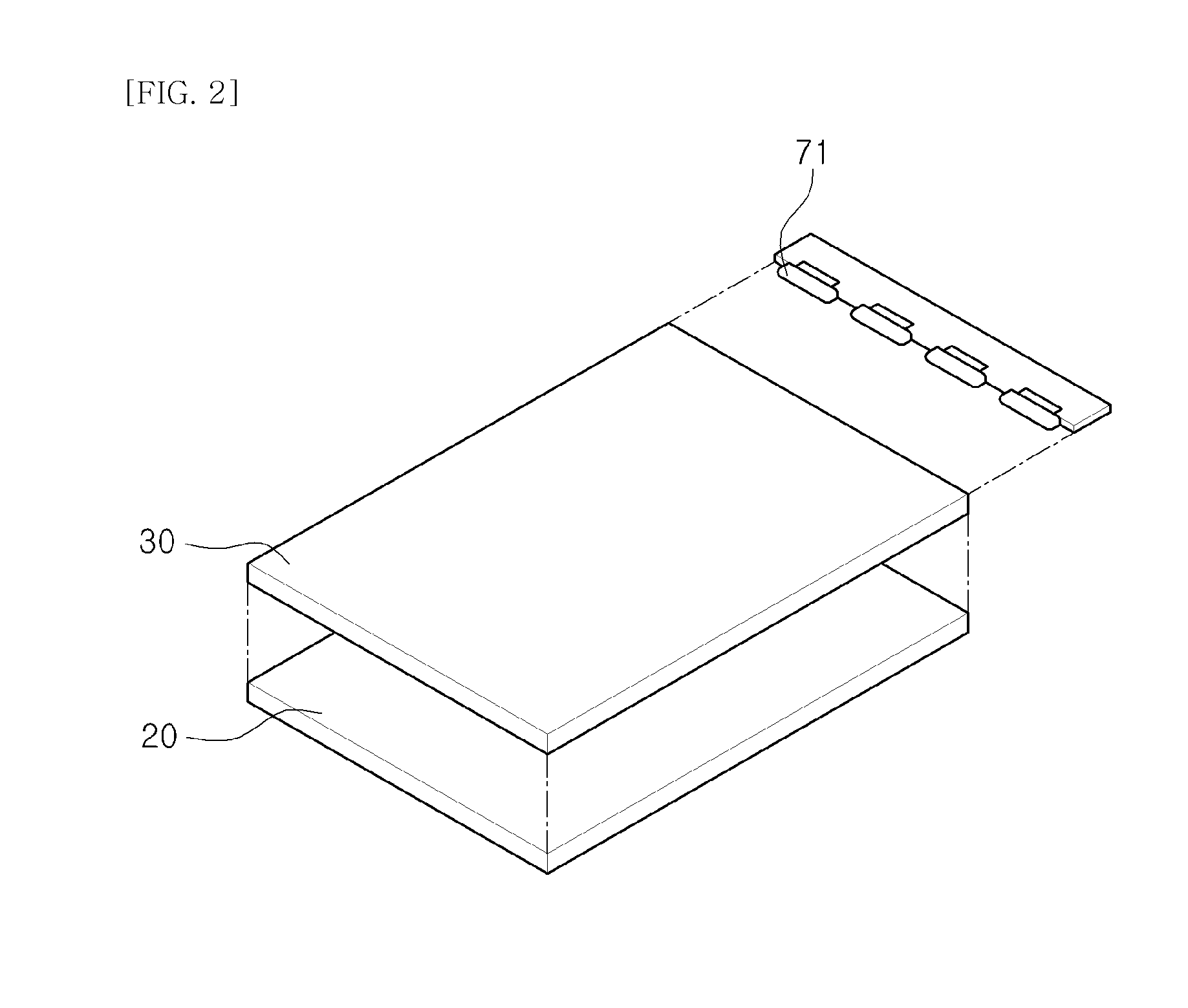
[0070]Each unit touch cell structure includes a conductive pad that fo...


PUM


Abstract

Provided is a touch cell structure for a touch panel in which a touch cell is configured into a new pad to gate mode in order to solve a problem of a conventional capacitive-type touch input device. The touch cell structure includes: a conductive pad that forms an electrostatic capacitance with respect to a touch unit when a finger of a human body or the touch unit having an electrical characteristic similar to the finger approaches the conductive pad within a predetermined distance; and a three-terminal type switching device whose gate terminal is connected with the conductive pad and whose output signal is changed in correspondence to a change in electric potential of the gate terminal of the three-terminal type switching device by the electrostatic capacitance between the touch unit and the conductive pad. Since the potential of the gate terminal of the switching device is determined by an electrostatic capacitance formed in the conductive pad, a difference of the output signal output from the switching device becomes large depending on whether a touch input occurs or not.

Description

TECHNICAL FIELD[0001]The invention relates to a touch cell structure of a touch panel and the touch panel using the same, and more particularly, to a touch cell structure having a very high detection sensitivity and accuracy for touch inputs as a specialized cell configuration, and employing a new pad to gate mode that can detect touch inputs in a digital mode and recognize multi-touch inputs and a touch panel using the same.BACKGROUND ART[0002]Usually, touch input devices are input devices which are respectively attached onto display devices such as LCDs (Liquid Crystal Displays), PDPs (Plasma Display Panels), OLED (Organic Light Emitting Diode) displays, and AMOLED (Active Matrix Organic Light Emitting Diode) displays or which are respectively built in the display devices and recognize touch input signals when an object such as a finger or pen contacts a respective screen on touch panels.[0003]Recent years, the touch input devices are respectively mounted on mobile devices such as...

Claims


Application Information

Patent Timeline
IPC IPC(8): G06F3/044H03K17/955
CPCG02F1/13338G06F2203/04104G06F3/044G06F3/0412G06F3/0443G06F3/0446G09G3/3648G06F3/04166
Inventor LEE, SUNG HO
Owner G2TOUCH CO LTD
Why Eureka
Try Eureka