Smart mirror apparatus using LCD panel

Inactive Publication Date: 2008-03-27
SODY
View PDF15 Cites 1 Cited by
  • Summary
  • Abstract
  • Description
  • Claims
  • Application Information

AI Technical Summary

Benefits of technology

[0016] The present invention has the following effects.
[0017] First, the response speed of an LCD mirror of the present invention is 0.3 seconds or less, which is at least 10 times faster than the conventional ECM rear view mirror.
[0018] Second, the light reflectance of the LCD mirror of the present invention, when in a bright state, is 40% or more and is increased by 60% or more compared to the conventional LCD mirror using polarizing sheets.
[0019] Third, because a portable battery may be used as the power source, a separate wire for co

Problems solved by technology

The critical points of this patent are limited to a light sensing technique and a technique of determining whether to operate the LCD.
To date, most commercialized electric mirrors for vehicles are products using the ECM technology, but electric mirrors using LCDs are not yet commercialized.
However, conventional ECM rear view mirrors, which have been produced, have a slow response speed in a range from 3 to 6 seconds and relatively high power consumption of several hundreds of mA.
Therefore, because the mirror is slightly dark even when not in operation, there is difficulty applying it to a mirror for vehicles.
In the case of an LCD mirror manufactured by coupling such an LCD panel to

Method used


Image

  • Smart mirror apparatus using LCD panel
  • Smart mirror apparatus using LCD panel
  • Smart mirror apparatus using LCD panel

Examples


Example

BEST MODE

[0029] Hereinafter, preferred embodiments of the present invention will be described in detail with reference to the attached drawings.

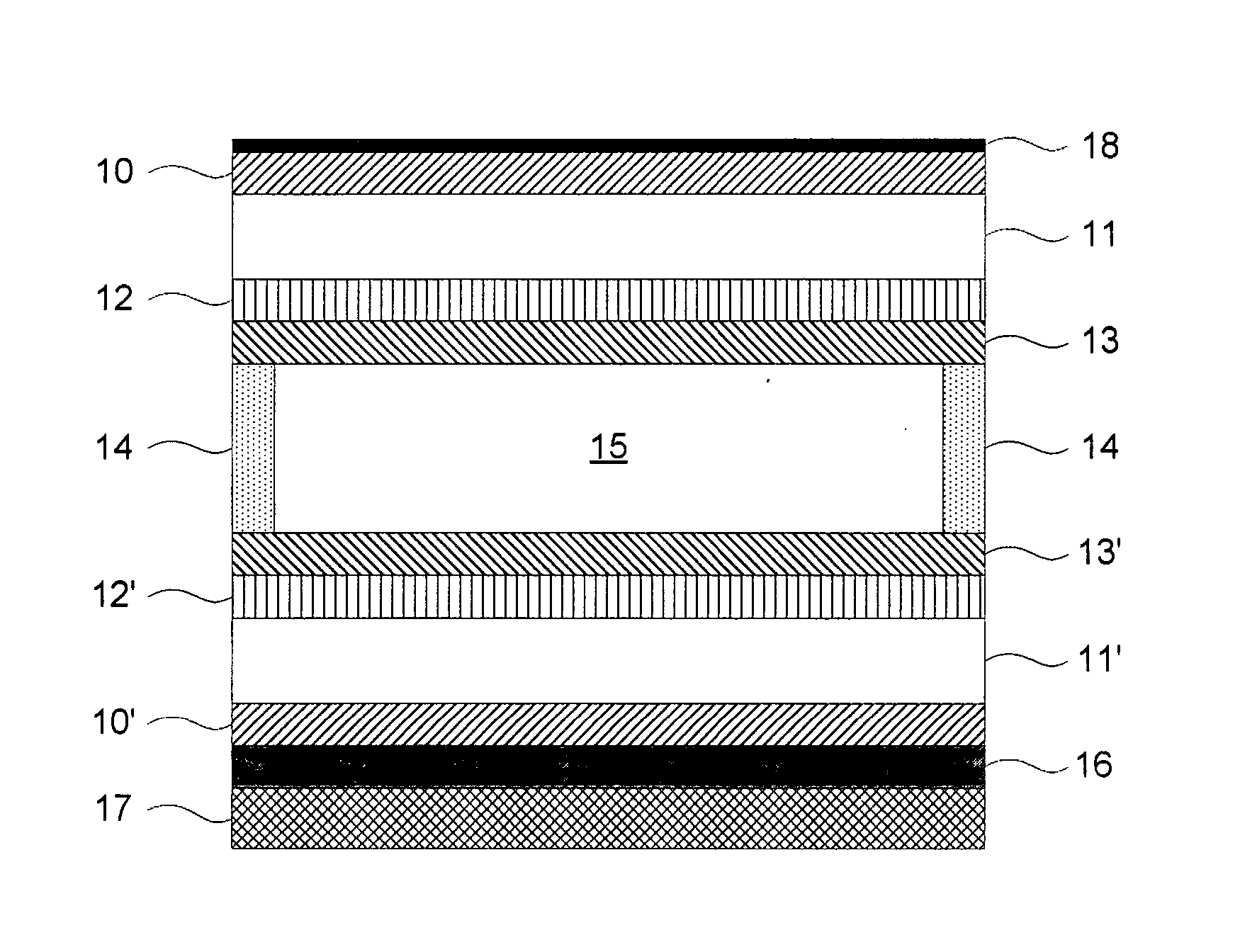
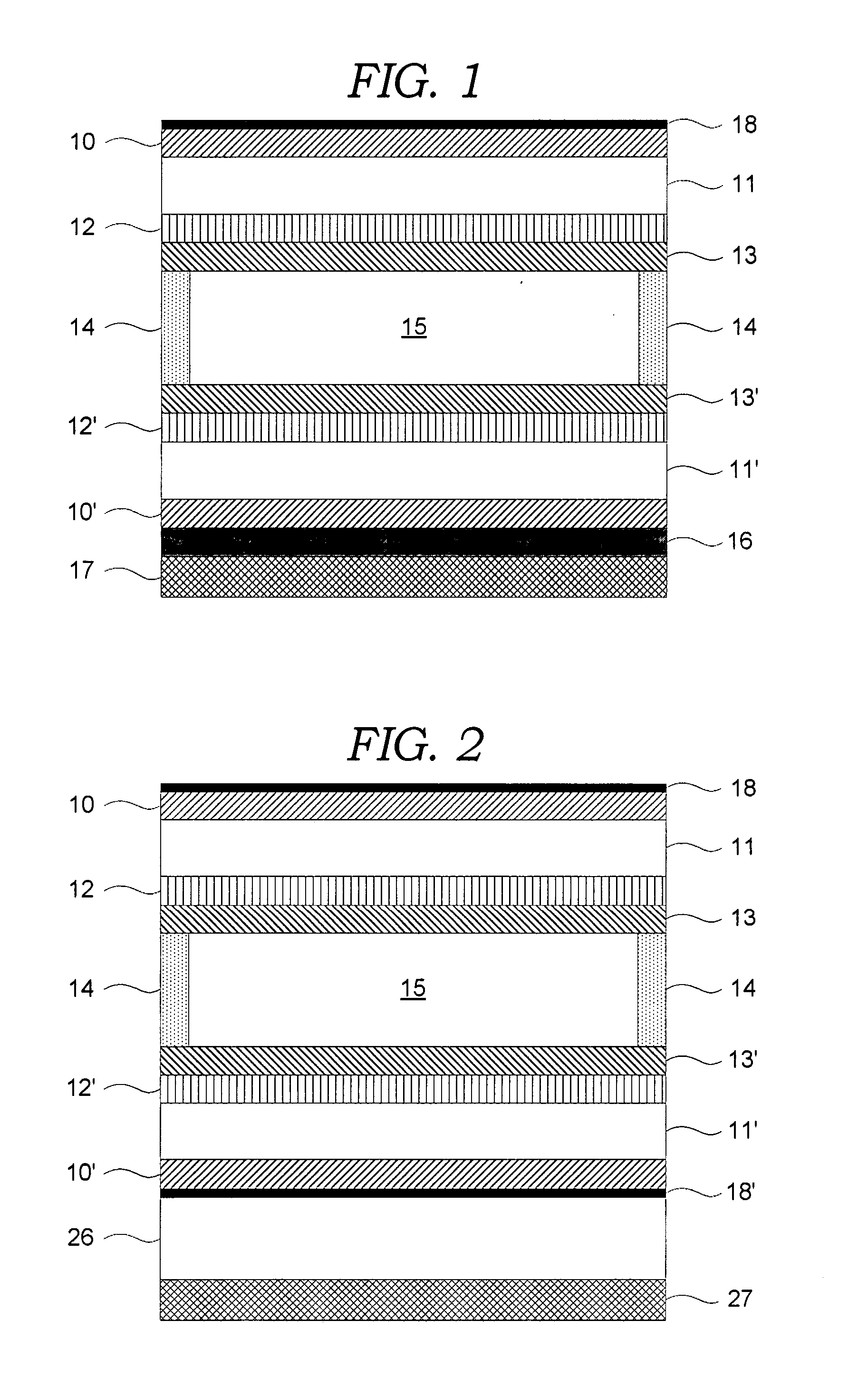
[0030]FIG. 1 is a sectional view showing an LCD mirror constituting a smart mirror apparatus, according to the first embodiment of the present invention. The LCD mirror includes an LCD panel. This LCD panel includes polarizing sheets 10 and 10′, transparent sheets 11 and 11′, transparent electrode layers 12 and 12′, orientation layers 13 and 13′, a sealant 14, and a liquid crystal layer 15. The LCD panel has a structure in which the polarizing sheet 10, the transparent sheet 11, the transparent electrode layer 12, the orientation layer 13, the liquid crystal layer 15 and the sealant 14, the orientation layer 13′, the transparent electrode layer 12′, the transparent sheet 11 and the polarizing sheet 10′ are consecutively laminated from the outside to the inside.

[0031] The polarizing sheet 10′, which is disposed inside the LCD panel, is att...


PUM


Abstract

The present invention provides a smart mirror apparatus using an LCD panel. The smart mirror of the present invention includes a reflective mirror, which is provided in the vehicle, and an LCD panel, which is placed in a light path between the reflective mirror and eyes of the driver and has one or two polarizing sheets. The smart mirror further includes an incident light detecting unit, which detects both the brightness of the incident light transmitted from the rear to the LCD panel and the brightness around the LCD panel, and calculates a difference value therebetween. The smart mirror further includes a voltage determination unit, which receives the calculated difference value and determines the drive voltage depending on the difference value, and a voltage apply and supply unit which applies the drive voltage, determined by the voltage determination unit, to the LCD panel.

Description

CROSS-REFERENCE TO RELATED APPLICATION [0001] This is a continuation application that claims benefit, under 35 USC §120, of co-pending International Application PCT / KR2006 / 000628, filed 23 Feb. 2006, designating the United States, and that claims foreign priority benefits under 35 USC §119(a) to Korean Patent Application No. 2005-0014867 filed 23 Feb. 2005, both of which are incorporated herein by reference.TECHNICAL FIELD [0002] The present invention relates to a smart mirror apparatus using an LCD panel, which adjusts the reflectance of an inside rear view mirror or a side rear view mirror of a vehicle, thus protecting the eyesight of a driver of the vehicle from strong light emitted from behind the vehicle at night, and preventing the light from dazzling the driver. BACKGROUND ART [0003] Conventional electric mirrors for vehicles mainly use an ECM (electrochromic material) technology. This technology was made well known through U.S. Pat. No. 4,902,108, U.S. Pat. No. 5,204,778, U....

Claims


Application Information

Patent Timeline
IPC IPC(8): G02F1/1335B60R1/08
CPCB60R1/088G02F1/1393G02F1/133533G02F1/13318
Inventor LEE, JONG CHEON
Owner SODY
Why Eureka
Try Eureka