LED panel lamp and manufacturing method of LED panel lamp

A technology of LED panel light and manufacturing method, which is applied in the direction of lampshade, printed circuit manufacturing, components of lighting devices, etc., can solve problems such as insufficient electrical response speed, thick conductive lines, affecting dynamic picture effects, etc., and achieve electrical response speed. Fast, fast charge transfer, good visual effect

Pending Publication Date: 2020-12-04
SUZHOU WEIYEDA TOUCH TECH +2
View PDF0 Cites 0 Cited by
  • Summary
  • Abstract
  • Description
  • Claims
  • Application Information

AI Technical Summary

Problems solved by technology

The conductive wires arranged in it are relatively thick, and the electrical response speed is not fast enough
As we all know, the speed of electrical response will affect the dynamic picture effect

Method used


Image

  • LED panel lamp and manufacturing method of LED panel lamp
  • LED panel lamp and manufacturing method of LED panel lamp
  • LED panel lamp and manufacturing method of LED panel lamp

Examples


Embodiment Construction

[0026] The specific implementation manners of the present invention will be further described in detail below in conjunction with the accompanying drawings and embodiments. The following examples are used to illustrate the present invention, but are not intended to limit the scope of the present invention.

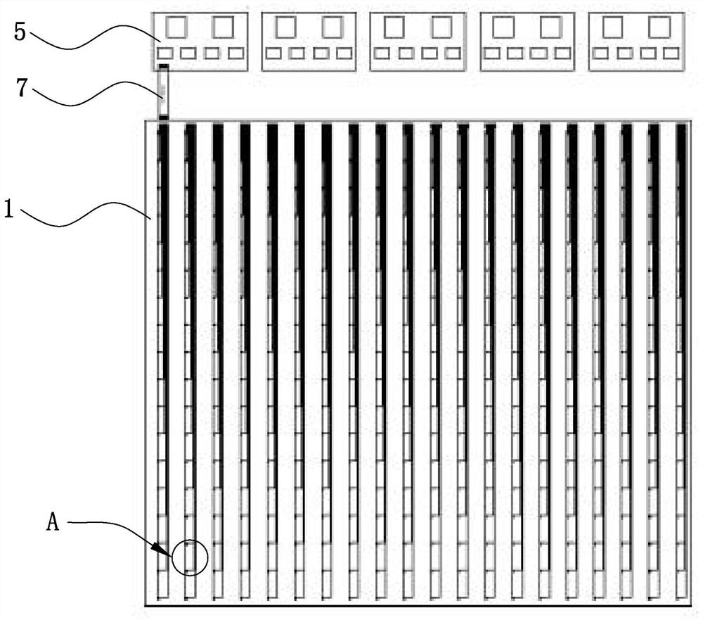
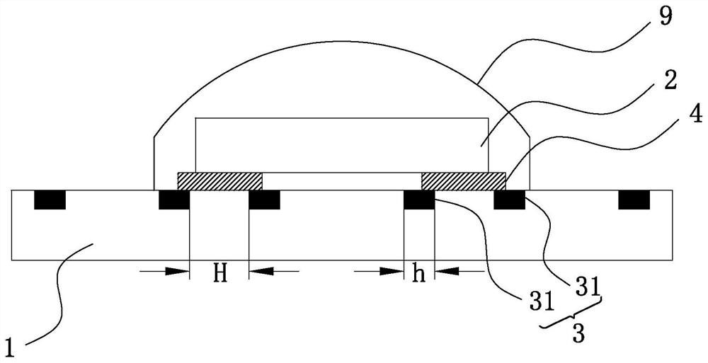
[0027] Please refer to Figure 1 to Figure 6 , the LED panel light provided in the embodiment of the present invention includes a flexible base film 1 , a plurality of circuits disposed on the flexible base film 1 , and a plurality of LED lamp beads 2 disposed on the flexible base film 1 . Each circuit is connected with at least one LED lamp bead 2 . The circuit is provided with at least two conducting wires 3 parallel to each other. Wherein, each conductive wire is composed of multiple secondary conductive wires 31, and the multiple secondary conductive wires 31 form a grid.

[0028] In this embodiment, each conductive wire 3 is designed as a grid-type conductive wire ...


PUM

PropertyMeasurementUnit
transmittivityaaaaaaaaaa

Abstract

The invention discloses an LED panel lamp. The LED panel lamp comprises a flexible base film, a plurality of circuits arranged on the flexible base film and a plurality of LED lamp beads arranged on the flexible base film, each circuit is connected with at least one LED lamp bead, each circuit is provided with at least two parallel conductive wires, each conductive wire is composed of a pluralityof secondary conductive wires, and a plurality of the secondary conductive wires form a grid. The invention further discloses a manufacturing method of the LED panel lamp. The method comprises the following specific steps: S1, providing the flexible base film; S2, manufacturing a plurality of grid type conductive wires on the flexible base film by utilizing a mold with an LED panel lamp circuit pattern, forming the circuit by a plurality of the conductive wires, and forming an LED panel lamp circuit by a plurality of the circuits; and S3, connecting the LED lamp beads with the conductive wiresin the circuits. The conductive wires are designed into a grid type, so that the electric response speed in a circuits is higher, and the LED panel lamp has a better visual sense during working.

Description

technical field [0001] The invention relates to the technical field of LEDs, in particular to an LED panel light and a method for manufacturing the LED panel light. Background technique [0002] Existing LED panel lights mostly use ITO (ITO Indium Tin Oxides, which is an N-type oxide semiconductor-indium tin oxide, and ITO thin film is indium tin oxide semiconductor transparent conductive film) conductive film wiring. The conductive wires it arranges are relatively thick, and the electrical response speed is not fast enough. As we all know, the speed of electrical response will affect the dynamic picture effect. [0003] The foregoing description is provided to provide general background information and does not necessarily constitute prior art. Contents of the invention [0004] The object of the present invention is to provide an LED panel light with fast electrical response and a method for manufacturing the LED panel. [0005] The present invention provides an LED p...

Claims


Application Information

Patent Timeline
Patent Type & Authority Applications(China)
IPC IPC(8): F21K9/20F21K9/66F21V19/00F21V23/00F21V3/06H01L33/56H05K3/10F21Y115/10
CPCF21K9/20F21K9/66F21V19/001F21V23/001F21V23/004F21V3/062H01L33/56H05K3/107F21Y2115/10F21Y2105/10H01L25/0753H01L33/62H01L33/58H01L2933/0066H05K1/189H05K2201/10106H05K2201/0376H05K2201/0108H05K1/0274H05K3/1258F21V19/0025F21V19/0045
Inventor 基亮亮刘麟跃周小红
Owner SUZHOU WEIYEDA TOUCH TECH
Why Eureka
Try Eureka