Solar decoration lamp

A decorative lamp and solar energy technology, which is applied to energy-saving lighting, identification devices, lighting devices, etc., can solve the problems of poor decoration and low aesthetics, and achieve the effects of high aesthetics, good decorative effect and easy installation.

Inactive Publication Date: 2017-05-24
HEILONGJIANG XINYICHENG NEW ENERGY TECH CO LTD
View PDF0 Cites 1 Cited by
  • Summary
  • Abstract
  • Description
  • Claims
  • Application Information

AI Technical Summary

Problems solved by technology

[0003] The purpose of the present invention is to provide a solar decorative lamp, which solves the common problems of poor decoration and low aesthetics in street lamps in the prior art. Design, not only has a good lighting function, but also has high aesthetics, good visual sense, and has a good decorative effect, and uses solar power, easy installation, high efficiency and energy saving

Method used


Image

  • Solar decoration lamp

Examples


Embodiment 1

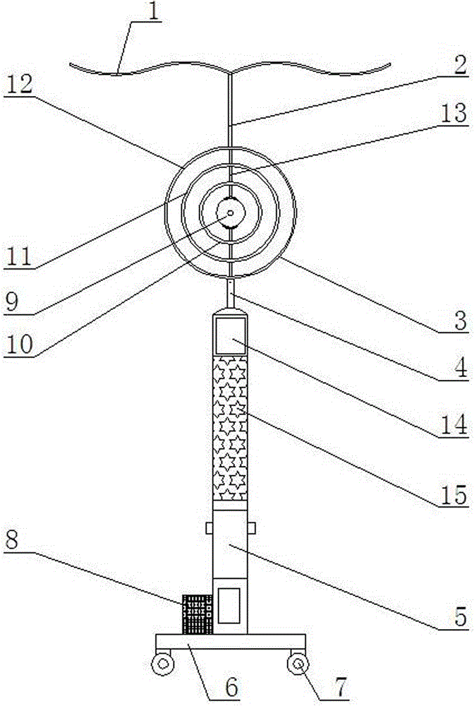
[0013] As shown in the figure, a solar decorative lamp includes a solar photovoltaic panel 1, an upper support rod 2, a circular lamp body 3, a lower support rod 4, a light pole 5, a base 6, a universal wheel 7, and a battery box 8, The solar photovoltaic panel 1 is composed of two left and right arc plates, and the bottom end is installed on the upper end of the circular lamp body 3 through the upper support rod 2; the bottom end of the circular lamp body 3 is installed on the lamp body through the lower support rod 4 The top of the pole 5 and the bottom end of the light pole 5 are installed on the base 6; four universal wheels 7 are installed at the four corners of the bottom of the base 6; 8 internal device battery pack.

Embodiment 2

[0015] As shown in the figure, the circular lamp body 3 is composed of a central lamp body 9, an inner circular lamp body 10, a middle circular lamp body 11, an outer circular lamp body 12, and a plurality of fixing rods 13; the central lamp body 9 Installed in the middle of the inner round lamp body 10, connected to the inner round lamp body 10 by two upper and lower fixed rods 13; Round lamp body 11; the Zhongyuan lamp body device is in the middle of the outer round lamp body 12, connected to the outer round lamp body 12 by two upper and lower fixing rods 13; the upper end of the outer round lamp body 12 is connected to the upper support rod 2, and the lower end is connected to the lower Support rod 4.

Embodiment 3

[0017] As shown in the figure, an LED display screen 14 is installed on the upper end of the front of the light pole 5, and a controller, a plurality of LED color light sources, and an inverter are installed inside the light pole 5; a plurality of five-pointed star hollow holes are arranged on the light pole 5 15. The inner side is a plurality of LED color light sources; the controller is connected to the inverter, the battery pack, the solar photovoltaic panel 1, the circular lamp body 3, the LED display screen 14, and a plurality of LED color light sources; the solar photovoltaic The board 1 is connected to the battery pack, the battery pack is connected to the inverter, the inverter is connected to the controller, and the controller is connected to the circular lamp body 3, the LED display screen 14, and multiple LED color light sources.


PUM


Abstract

The invention discloses a solar decoration lamp. The solar decoration lamp comprises a solar photovoltaic plate, an upper support rod, an annular lamp body, a lower support rod, a lamp rod, a base, universal wheels and an accumulator box; the solar photovoltaic plate consists of left and right two arc plates, and the bottom end is arranged at the upper end of the annular lamp body through the upper support rod; the bottom end of the annular lamp body is arranged at the top end of the lamp rod through the lower support rod; the bottom end of the lamp rod is arranged on the base; four universal wheels are arranged at four corners of the bottom end of the base; the accumulator box is arranged at the left lower end of the lamp rod on the left side of the top end of the base; and an accumulator set is arranged in the accumulator box. The solar decoration lamp solves the problems of weak decoration and lower beauty in a street lamp in the prior art, adopts the designs of the arc solar panel, the annular lamp body and hollow color lamps, is excellent in illuminating function, higher in beauty, better in visual sense and excellent in decorating effect, adopts solar energy to supply electricity, is convenient to install, is high in efficiency, and saves the energy.

Description

technical field [0001] The invention relates to the field of lamp manufacturing, in particular to a solar decorative lamp. Background technique [0002] As one of the lighting equipment, street lamps have been widely used in our daily life, but the existing street lamps generally only adopt a single structure design of lamp pole and lamp holder, which only meets the lighting needs, but its aesthetics is poor and the decorative effect is poor. There are still deficiencies; secondly, the existing street lamps are still generally powered by mains electricity. During installation, a large number of cables need to be laid, the cost of wiring is high, and more manpower and material resources are required to complete the installation, which is time-consuming and laborious. , there is also the problem of inconvenient maintenance; in addition, the existing street lamps mostly use a single light source for lighting, the lighting effect is poor, and the night landscape level is not ric...

Claims


Application Information

Patent Timeline
Patent Type & Authority Applications(China)
IPC IPC(8): F21S9/03F21V21/10F21V21/06F21V17/10G09F9/33F21W131/103F21Y115/10
CPCY02B20/72F21S9/035F21V17/10F21V21/06F21V21/10F21W2131/103G09F9/33
Inventor 胡晶王永刚
Owner HEILONGJIANG XINYICHENG NEW ENERGY TECH CO LTD
Why Eureka
Try Eureka