Liquid crystal display apparatus

a liquid crystal display and display device technology, applied in non-linear optics, instruments, optics, etc., can solve the problems of lowering the viewing angle performance of dark images, unable to disclose the application of different alignments, and unable to completely eliminate dependencies, so as to improve the receiving state of portable tvs and improve quality

Inactive Publication Date: 2009-02-03
PANASONIC LIQUID CRYSTAL DISPLAY CO LTD +1
View PDF3 Cites 40 Cited by
  • Summary
  • Abstract
  • Description
  • Claims
  • Application Information

AI Technical Summary

Benefits of technology

[0015]The foregoing location causes the location of the polarizer and the liquid crystal layer in the transmissive display portion to be likewise to the transmissive IPS liquid crystal display apparatus. This makes it possible to obtain the same applied voltage characteristic of a normally closed type (in which type the dark image appears when the applied voltage is zero) and the same transmissive display of the wide viewing angle as those of the transmissive IPS liquid crystal display apparatus.
[0017]For aligning both of the reflective display portion and the transmissive display portion homogeneously and making the alignment direction of one display portion different by 45 degrees from that of the other display portion, it is necessary to divide the alignment direction on two boundaries of the liquid crystal layer. This makes the manufacturing process intricate. The reflective display portion is adjusted to keep a twisted alignment of 45 degrees, form a degree of 45 between only the border closer to the light incident plane and the liquid crystal alignment direction of the transmissive display portion, and keep the liquid crystal alignment direction same as that of the transmissive display portion on the opposite border. Also in this case, if the twisted pitch of the liquid crystal layer in the reflective display portion is long enough, the liquid crystal layer and the polarizer closer thereto are functioned as a circular polarizer, which results in realizing the normally closed applied voltage characteristic. Further, since the division of the alignment is carried out on the border of one side, the manufacturing process is made simpler.
[0019]In the case of displaying a color image through the use of color filters, each color filter allows only the ray of light with about one third as long a wavelength range as the visible wavelength range to be mainly passed. By making the liquid crystal thickness of the reflective display portion variable in respective color filters by changing the layer thickness of the color filter according to each color and making the retardation of the liquid crystal layer a quarter wave in the essential transmissive wavelength of each color filter, it is possible to sufficiently absorb light of a substantially overall visible wavelength, thereby being able to eliminate the coloring of the dark image.
[0022]For example, consider the case that the liquid crystal alignments of the reflective display portion and the transmissive display portion are homogeneous. In a case that the direction of a combshaped pixel electrode of the reflective display portion is the same as that of the transmissive display portion, by keeping the angle formed between the electric field applying direction and the liquid crystal alignment direction 67.5 degrees, the angle formed between the electric field applying direction and the liquid crystal alignment direction in the reflective display portion is made equal to the angle in the transmissive display portion. However, the angle of 67.5 degrees makes the effective permittivity anisotropy of the liquid crystal layer small and thereby often makes the threshold voltage too high. For example, the angle of 75 degrees both in the reflective display portion and the transmissive display portion makes it possible to reduce the threshold voltage. In order to realize this, the direction of the combshaped pixel electrode in the reflective display portion may be made different from that in the transmissive display portion.
[0024]The liquid crystal display apparatus according to the present invention allows a user to carry a high-quality display device like an ordinary monitor. The application of this liquid crystal display apparatus to the display device of a portable phone also allows high-quality image information to be reproduced and a user to treat image information of higher quality. The use of this high-quality display device for a digital camera makes it easy to make sure of an image before being shot and / or a shot image. In future, it is presumed that the prevail of the surface wave digital broadcast leads to greatly improving the receiving state of the portable TV. The use of this liquid crystal display apparatus for a portable TV makes it possible to reproduce the high-quality image information at any place.

Problems solved by technology

However, the dependency cannot be completely eliminated.
However, it does not disclose the application of those different alignments to the IPS system that provides a transmissive display with a wide viewing angle.
However, since the phase plate is located between the liquid crystal layer and the polarizer, the extra phase difference occurs in the viewing angle direction, which leads to lowering the viewing angle performance on the dark image.

Method used


Image

  • Liquid crystal display apparatus
  • Liquid crystal display apparatus
  • Liquid crystal display apparatus

Examples


first embodiment

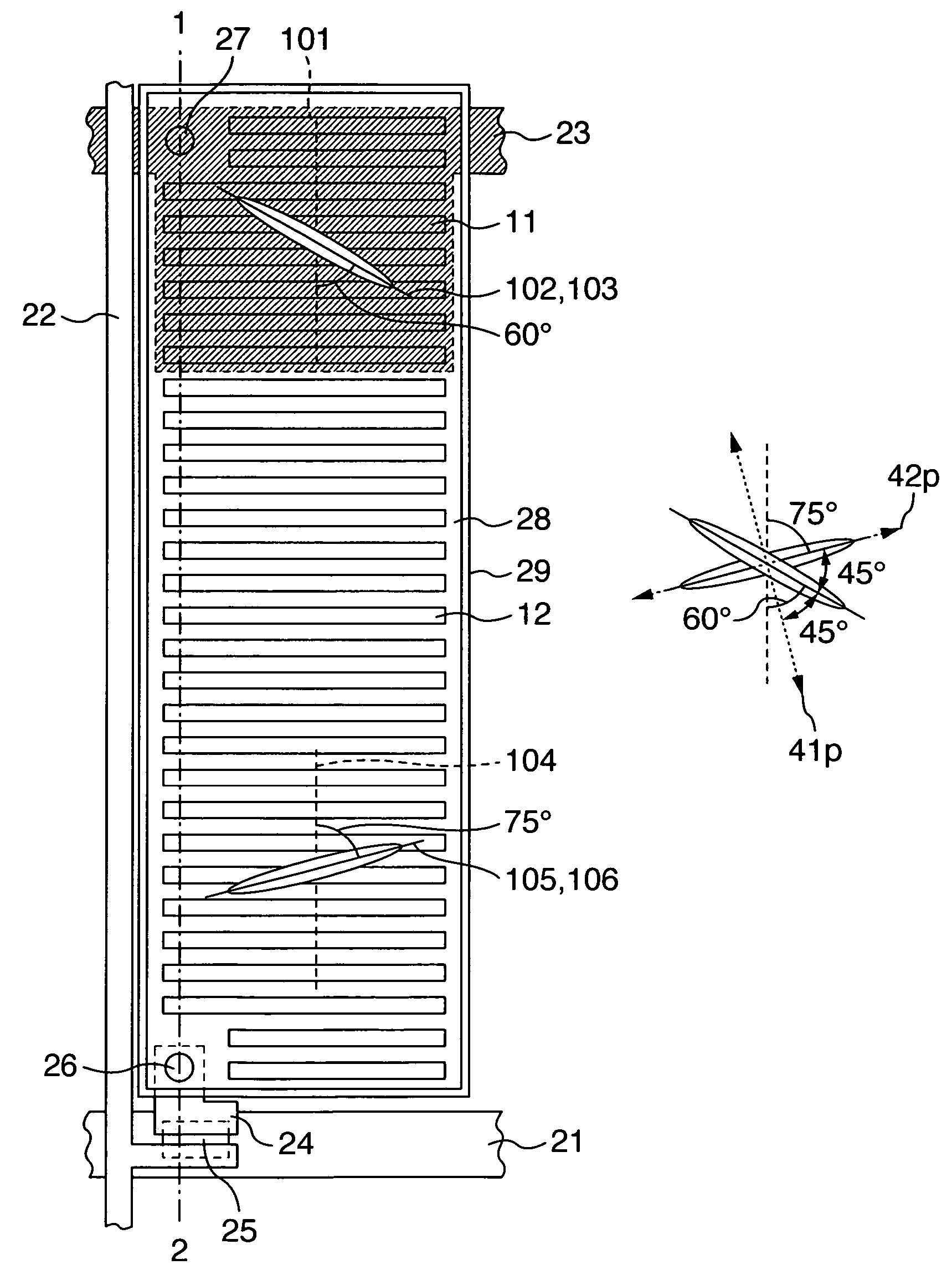
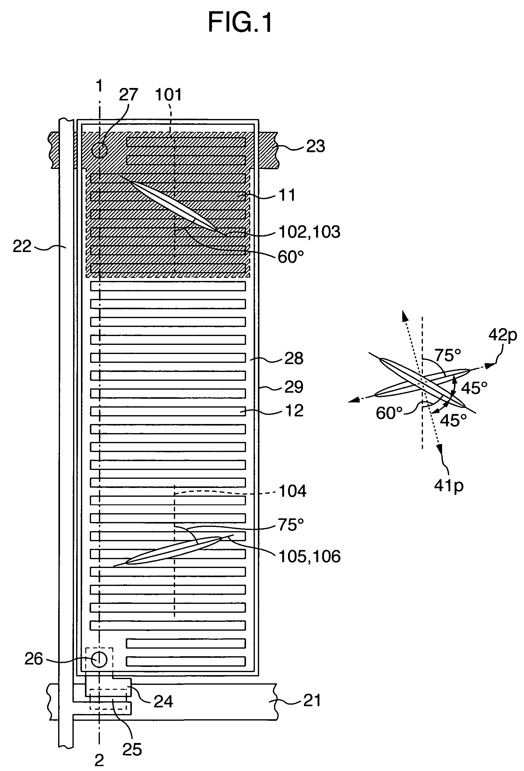
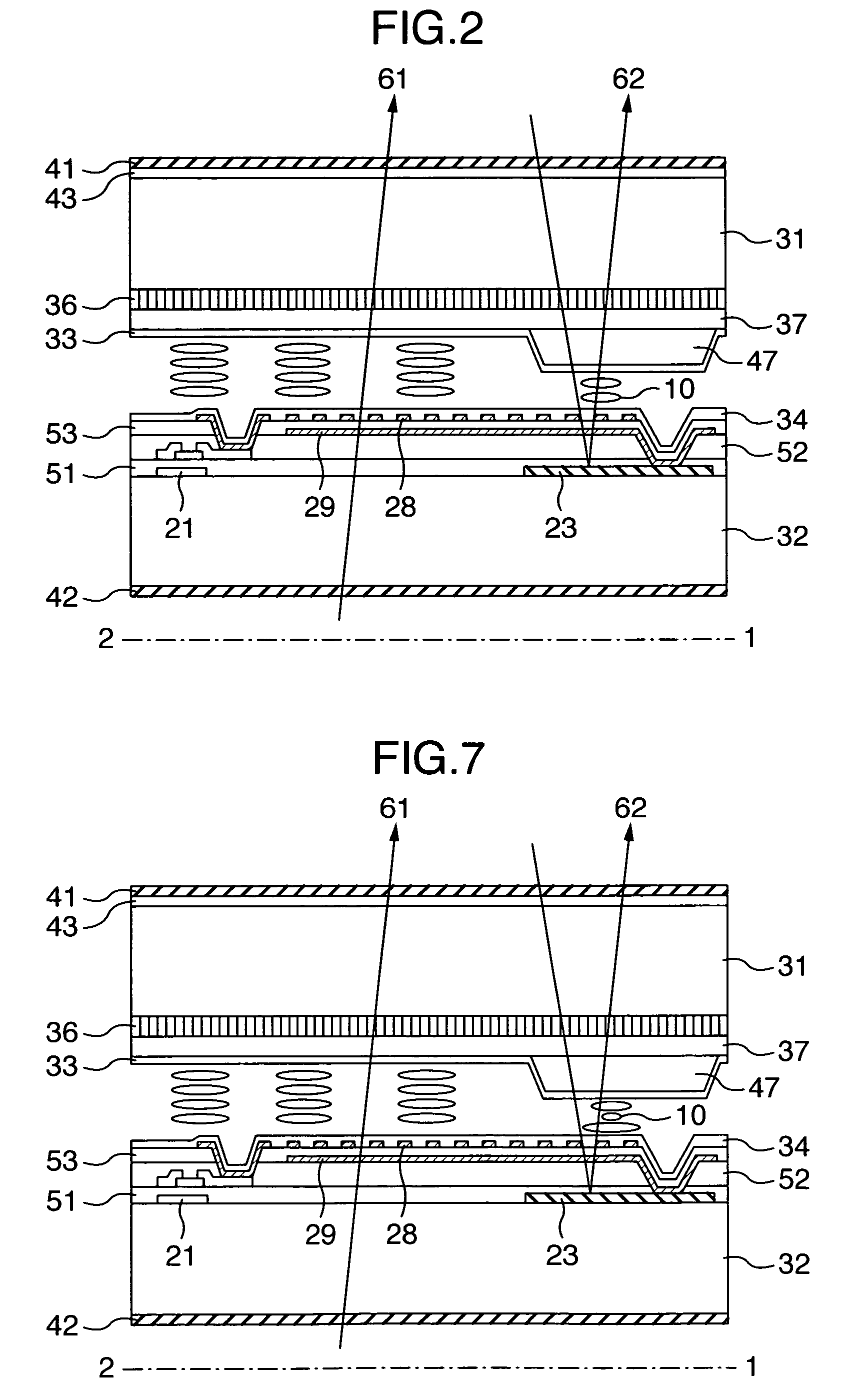
[0052]A section of one of the pixels composing the liquid crystal display (referred to as LCD) apparatus according to the present invention is illustrated in FIG. 2. A top view of a second substrate 32 shown in the section of FIG. 2 is illustrated in FIG. 1, in which view the second substrate 32 is observed from the normal direction. The section of FIG. 1 on a dashed line 1-2 corresponds to FIG. 1. As shown in FIG. 2, the LCD apparatus according to the present invention is mainly composed of a first substrate 31, a liquid crystal layer 10 and the second substrate 32, in which apparatus the liquid crystal layer 10 is laid between the first and the second substrates 31 and 32.

[0053]The first substrate 31 includes a color filter 36, a leveling layer 37 and a first alignment layer 33 on the side closer to the liquid crystal layer 10. The second substrate 32 includes a thin film transistor on the side closer to the liquid crystal layer 10. The thin film transistor is connected with a sca...

second embodiment

[0088]In the first embodiment, the reflective display portion has the different alignment direction of the liquid crystal from the transmissive display portion. Hence, in both of the first and the second alignment layers 33 and 34, the reflective display portion and the transmissive display portion are respectively treated by the rubbing technique with a mask. This treatment results in increasing the steps of the manufacturing process.

[0089]The alignment direction and the liquid crystal alignment state in the reflective display portion and the transmissive display portion of the LCD apparatus according to this embodiment are shown in FIG. 6. In this embodiment, only the first alignment layer 33 is differently aligned between the reflective display portion and the transmissive display portion. The second alignment layer 34 is uniformly aligned on the overall surface. This results in reducing the steps of the manufacturing process. That is, like the first embodiment, for the first ali...

third embodiment

[0096]The top view of the LCD apparatus according to this embodiment is shown in FIG. 9. In this embodiment, each of the pixel electrode 28 and the common electrode 29 is formed in a combshaped manner and both of the electrodes are formed in the same layer. This makes it possible to form the arched electric field between the pixel electrode 28 and the common electrode 29 when a voltage is applied, thereby causing the electric field to drive the liquid crystal layer.

[0097]The combshaped structure of each electrode 28 or 29 is formed in parallel to the signal electrode 22 in any of the reflective display portion and the transmissive display portion. Hence, the electric field direction 101 of the reflective display portion and the electric field direction 104 of the transmissive display portion are vertical to the signal electrode 22. In association with this direction, the alignment directions of the reflective display portion and the transmissive display portion were set as shown in ...


PUM

PropertyMeasurementUnit
angleaaaaaaaaaa
wavelengthaaaaaaaaaa
thicknessaaaaaaaaaa

Abstract

A liquid crystal display apparatus includes a transmissive display portion having the same liquid crystal alignment directions and transmissive axes of the polarizers as the transmissive IPS liquid crystal display apparatus. Further, the liquid crystal layer of its reflective display portion has a retardation of a quarter wave. The liquid crystal alignment directions of the reflective display portion are set to be crossed with the transmissive axes of the polarizers in the transmissive display portion at an angle of 45 degrees.

Description

CROSS-REFERENCE TO RELATED APPLICATION[0001]This application relates to U.S. patent application Ser. No. not yet assigned based on Japanese Patent Application No. 2004-154691 filed May 25, 2004 entitled “LIQUID CRYSTAL DISPLAY APPARATUS” by Osamu ITO et al., the disclosure of which is incorporated herein by reference.BACKGROUND OF THE INVENTION[0002]The present invention relates to a liquid crystal display apparatus capable of displaying an image in various kinds of environments in ranges from a light place to a dark place and realizing a high-quality transmissive display at a wide viewing angle.[0003]Today, a transmissive liquid crystal apparatus with a wide viewing angle of such as an IPS (In-plane Switching) or an VA (Vertical Alignment) liquid crystal display is prevailing as a monitor. Such a liquid crystal apparatus with improved response performance is also used as a television. On the other hand, the liquid crystal display apparatus is also prevailing in the field of portabl...

Claims


Application Information

Patent Timeline
Patent Type & Authority Patents(United States)
IPC IPC(8): G02F1/1335G02F1/1337G02F1/1343
CPCG02F1/133528G02F1/134363G02F1/133707G02F1/133555G02F2001/133757G02F1/133757
Inventor ITOU, OSAMUTANNO, JUNJIIMAYAMA, HIROTAKAOCHIAI, TAKAHIROMORIMOTO, MASATERU
Owner PANASONIC LIQUID CRYSTAL DISPLAY CO LTD
Why Eureka
Try Eureka