Method of forming sole and sole structure with shoe nail coupled thereto and sole structure with shoe nail

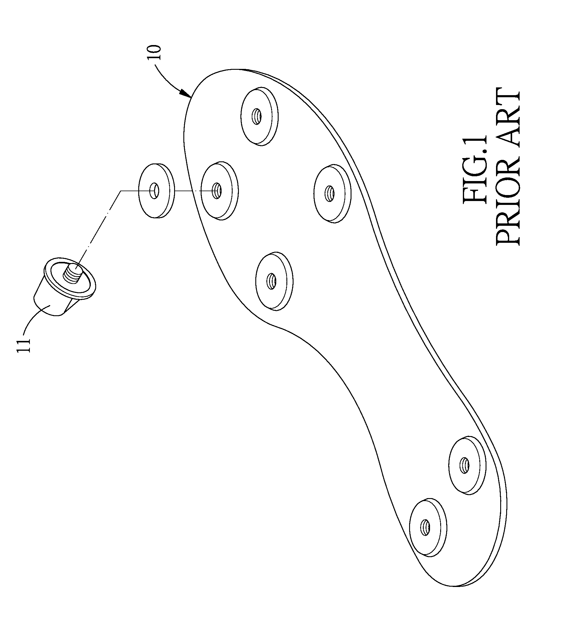
a technology of sole structure and shoe nail, which is applied in the field of manufacturing parts and components of shoes, can solve the problems of unfit mass production, unsuitable for mass production and achieve the effects of low coupling stability, insufficient grip, and complex manufacturing process

Inactive Publication Date: 2016-04-28
YANG TENG JEN
View PDF3 Cites 0 Cited by
  • Summary
  • Abstract
  • Description
  • Claims
  • Application Information

AI Technical Summary

Benefits of technology

[0007]The present invention provides a method of forming a sole and a sole structure with shoe nails coupled thereto and the sole structure with the shoe nails to overcome drawbacks of the prior art, namely intricate manufacturing process, insufficient grip, and low coupling stability.
[0016]The present invention is characterized in that: pre-formed shoe nails and thermally molten plastic are disposed in an injection molding mold, and an injection molding process is performed to form a sole and couple the shoe nails and the sole together, so easily as to increase production efficiency and economic benefits.

Problems solved by technology

The aforesaid manufacturing process is intricate and thus unfit for mass production.
However, although shoe nails are different from a sole in material characteristics, both the shoe nails and the sole are made of plastic; as a result, the grip of the shoe nails is not up to standard, and thus there is still room for improvement.
Since rubber differs from plastic in terms of forming conditions and manufacturing techniques, conventional forming techniques are unfit to form a rubber part and a plastic part simultaneously, and thus it is necessary to pre-form the rubber parts and the plastic part separately before performing a dispensing and adhering procedure or a coupling procedure on the rubber part and the plastic part separately.
A failure to control precisely the degree of uniformity in dispensing the plastic during the dispensing step leads to low coupling stability.

Method used


Image

  • Method of forming sole and sole structure with shoe nail coupled thereto and sole structure with shoe nail
  • Method of forming sole and sole structure with shoe nail coupled thereto and sole structure with shoe nail
  • Method of forming sole and sole structure with shoe nail coupled thereto and sole structure with shoe nail

Examples


Embodiment Construction

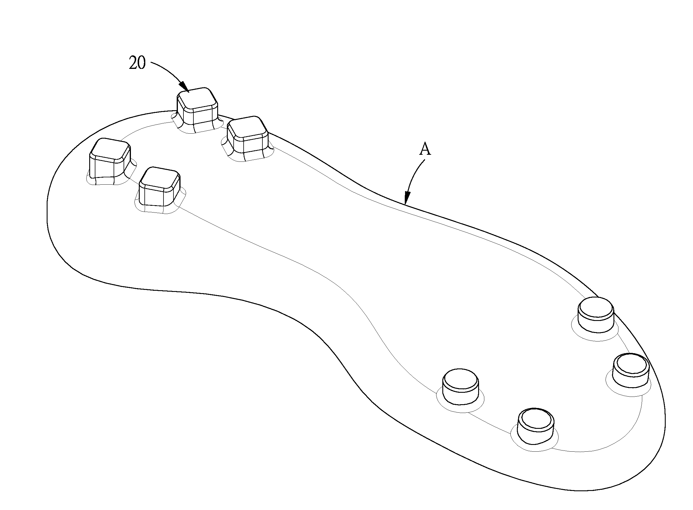
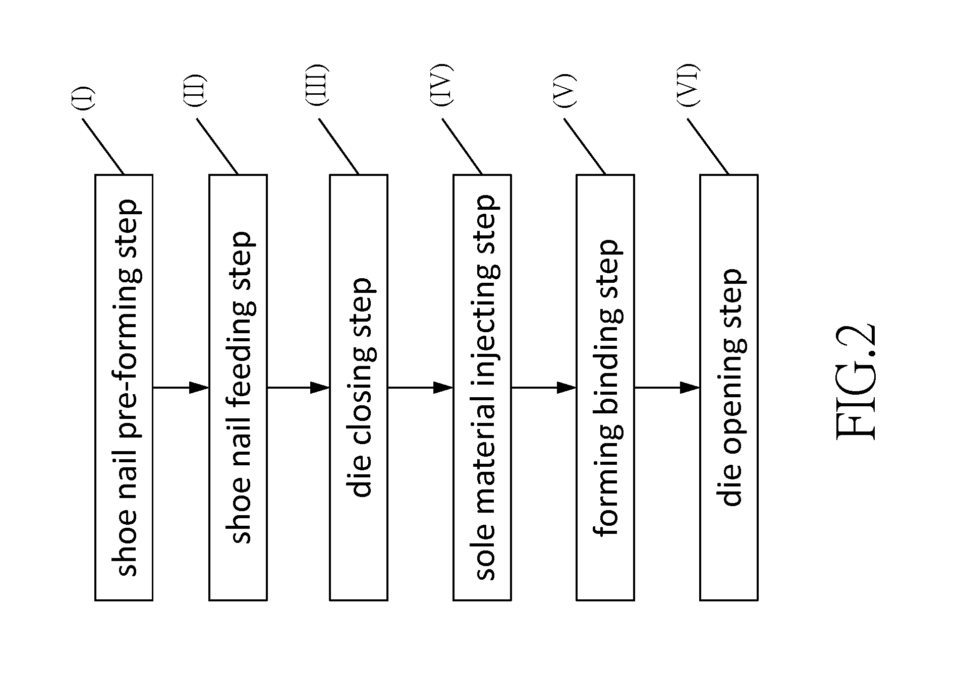
[0025]The present invention provides a method of forming a sole and a sole structure with shoe nails coupled thereto, as shown in FIGS. 2-6. The method comprises the steps below.

[0026]Shoe nail pre-forming step (I): forming a shoe nail 20. In this embodiment, the shoe nail 20 is made of rubber. The shoe nail 20 has a head 21 and a coupling segment 22. The coupling segment 22 extends in an axial direction X. A radial direction Y is perpendicular to the axial direction X. The outer diameter of the coupling segment 22 is less than the outer diameter of the head 21, such that a filling ring portion 23 is formed between the head 21 and the coupling segment 22. One end of the coupling segment 22 is connected to the head 21. A slot 221 is disposed at the other end of the coupling segment 22, wherein the slot-disposed end of the coupling segment 22 is different from the head-connected end of the coupling segment 22. The slot 221 has a slot bottom 222 and a slot inner diameter D1. The slot 2...


PUM

PropertyMeasurementUnit
outer diameteraaaaaaaaaa
inner diameteraaaaaaaaaa
coupling stabilityaaaaaaaaaa

Abstract

A method of forming a sole and a sole structure with shoe nails coupled thereto and the sole structure with the shoe nails are provided. The method includes pre-forming shoe nails, putting the shoe nails in an injection molding mold, injecting a thermally molten sole material into a mold in a manner that the sole material covers inner and outer surfaces of the shoe nails, and performing a cooling process whereby the sole material solidifies and turns into a sole which is then coupled to the shoe nails. The method enables a sole with shoe nails to be quickly manufactured so easily that it increases production efficiency and economic benefits.

Description

BACKGROUND OF THE INVENTION[0001]1. Technical Field[0002]The present invention relates to methods of manufacturing parts and components of shoes, and more particularly, to a method of forming a sole and a sole structure with shoe nails coupled thereto and the sole structure with the shoe nails.[0003]2. Description of Related Art[0004]Shoe nails, also known as foot nails, are disposed mostly in a sole of a football shoe or a track and field sports shoe to reduce vibration, increase grip, and enhance control. Referring to FIG. 1, a conventional sole 10 with a plurality of shoe nails 11 coupled thereto. The shoe nails 11 are made of metal. The shoe nails 11 are each fastened to the sole 10 by a bolt 111, and then the sole 10 is coupled to a shoe body. The aforesaid manufacturing process is intricate and thus unfit for mass production.[0005]In view of this, a method of manufacturing a sole with shoe nails was disclosed, which requires performing an instance of injection molding using tw...

Claims


Application Information

Patent Timeline
Patent Type & Authority Applications(United States)
IPC IPC(8): A43D69/00A43B13/28
CPCA43D69/00A43B13/28A43B5/02A43B13/26A43C15/16B29D35/128B29D35/122A43B13/04
Inventor YANG, TENG-JEN
Owner YANG TENG JEN
Why Eureka
Try Eureka