Latency counter, semiconductor memory device including the same, and data processing system

a technology of latency counter and memory device, applied in the field of latency counter, can solve the problems of inability to synchronize the operation of the two ring counters, and inability to shorten the time from issuing a read command

Active Publication Date: 2010-11-02
LONGITUDE LICENSING LTD
View PDF5 Cites 40 Cited by
  • Summary
  • Abstract
  • Description
  • Claims
  • Application Information

AI Technical Summary

Benefits of technology

[0012]Still another object of the present invention is to provide a latency counter capable of sufficiently securing an operation margin even when a frequency of a clock is high, and a semiconductor memory device including the same.
[0017]Types of the counter included in the frequency-divided counter are not particularly limited, and the counter that outputs a count value in a binary format, e.g., a ripple counter, can be used. When the ripple counter is used, there is a problem in that a change is delayed more in higher-order bits at a time of incrementing or decrementing. However, in the present invention, a count operation is performed based not on the internal counter itself but on a frequency-divided clock obtained by dividing the internal counter. Thus, it is possible to sufficiently absorb a delay of high-order bits. In addition, the number of bits itself of the ripple counter can be reduced by the frequency division, and thus, as compared to a case that no frequency division is performed, a delay itself of a most significant bit can be decreased.
[0019]Thus, according to the present invention, the counting of the latency is performed based not on the internal clock itself but on the divided clock obtained by frequency-dividing the internal clock. Thus, even when the frequency of the clock is high, it is possible to sufficiently secure an operation margin.
[0021]Accordingly, even when the count value jumps, there is no influence to the count operation of the latency at all. That is, the counter is automatically restored, and thus, it becomes possible to continue the normal operation without restarting.

Problems solved by technology

However, so long as a DRAM core performs an analog operation also in the synchronous DRAM, a considerably weak charge needs to be amplified based on a sense operation.
Accordingly, it is not possible to shorten a time from issuing a read command until outputting first data.
However, when different ring counters, i.e., one for input and the other for output, are used, if a frequency of a clock becomes high, synchronizing operations of the two ring counters become difficult.
It sometimes becomes also impossible to simultaneously reset the two ring counters at a reset time.
Accordingly, there arises a problem in that a count number of the latency is deviated, resulting in a malfunction.
However, as a result of further researches by the inventor, it was found that the ring counter itself probably malfunctioned in some cases.
However, at a time of entering a self-refresh mode or a power-down mode, a hazard is sometimes outputted to an internal clock depending on a certain timing.
As a result, the ring counter can be in an unstable state.
When the ring counter is in an unstable state, an error occurs that the active level is latched to a plurality of latch circuits or a non-active level is latched to all the latch circuits.
Such an error cannot be removed until when the entire memory is restarted.
Accordingly, the latency counter cannot perform a normal operation any more without restarted.

Method used


Image

  • Latency counter, semiconductor memory device including the same, and data processing system
  • Latency counter, semiconductor memory device including the same, and data processing system
  • Latency counter, semiconductor memory device including the same, and data processing system

Examples


Embodiment Construction

[0036]Preferred embodiments of the present invention will now be explained in detail with reference to the drawings.

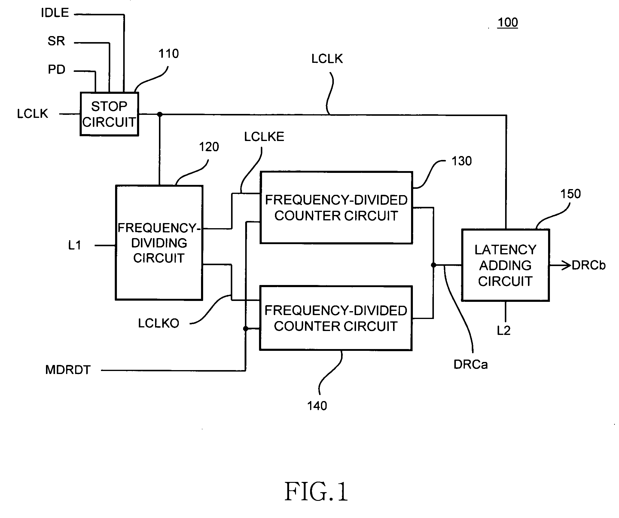
[0037]FIG. 1 is a circuit diagram of a latency counter 100 according to a preferred embodiment of the present invention.

[0038]The latency counter 100 according to the present embodiment is a counter (CL counter) that counts a CAS latency of a read command at the time of a read operation. However, a subject counter to which the present invention is applied is not limited thereto.

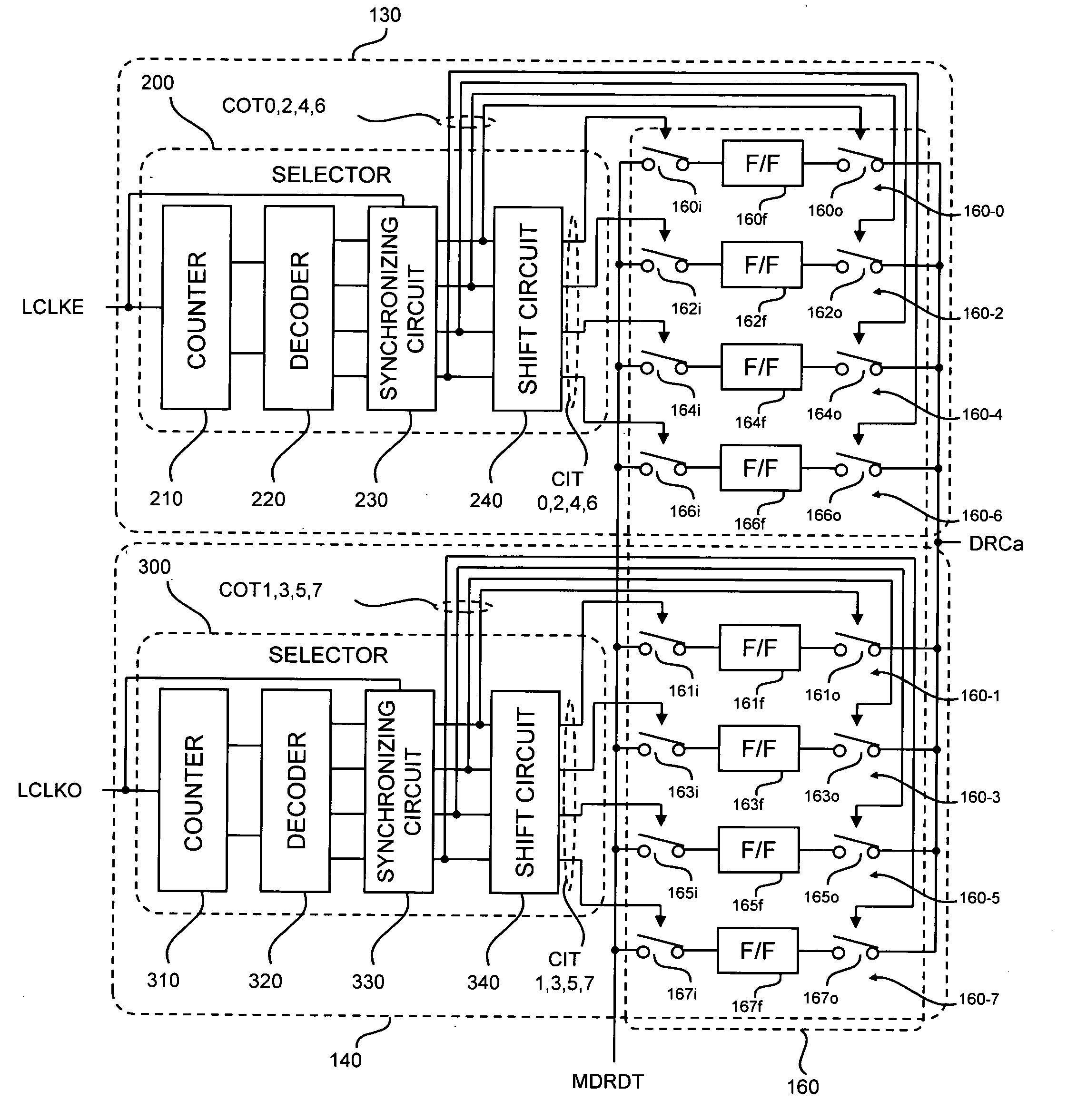
[0039]As shown in FIG. 1, the latency counter 100 includes: a frequency-dividing circuit 120 that generates divided clocks LCLKE and LCLKO based on an internal clock LCLK; frequency-divided counter circuits 130 and 140 that count a latency of an internal command MDRDT based on the respectively corresponding divided clocks LCLKE and LCLKO; and a latency adding circuit 150 capable of adding the latency of the internal command MDRDT by one clock cycle.

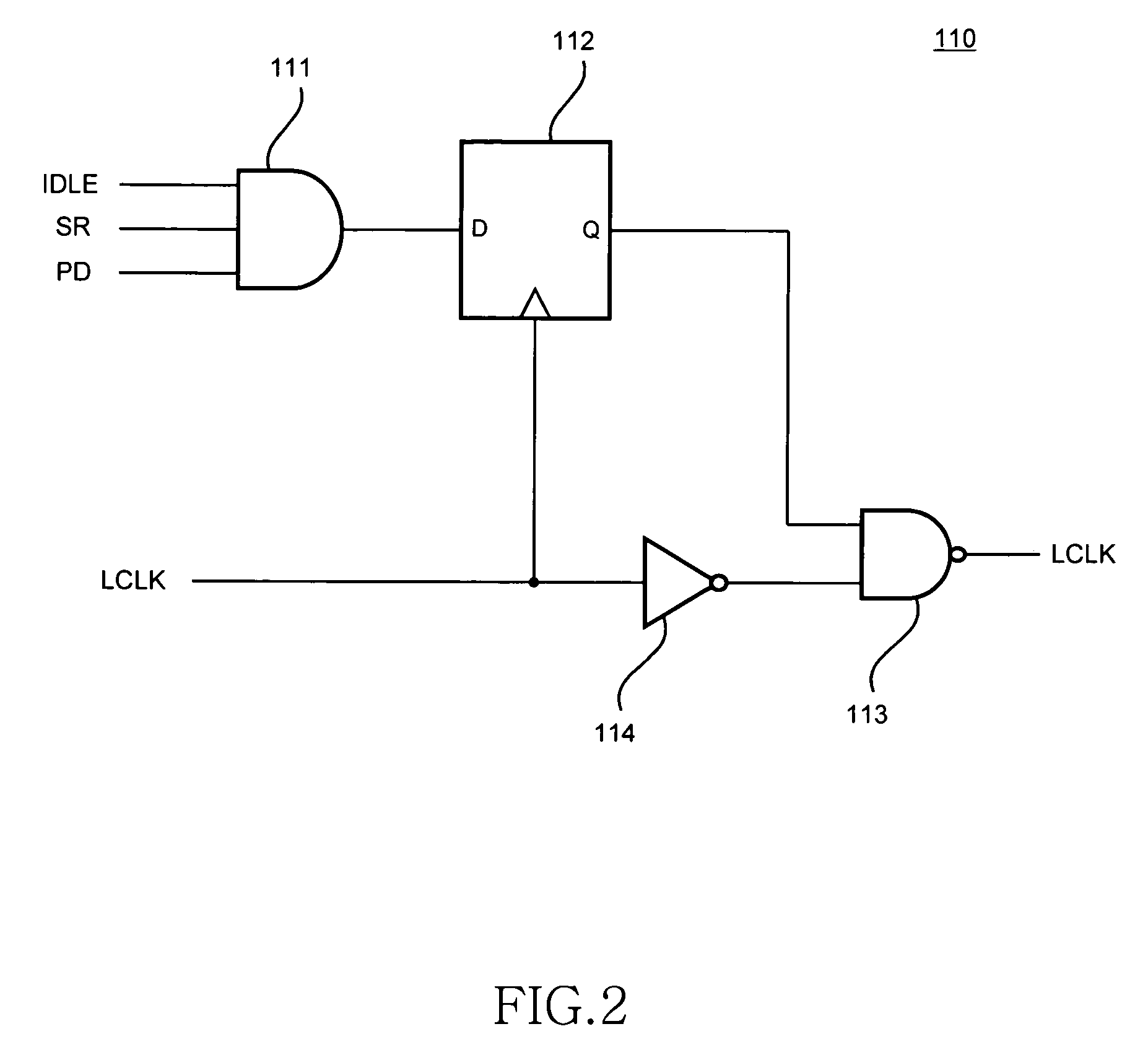
[0040]The internal clock LCLK is generated by a...


PUM


Abstract

A latency counter includes: a frequency-dividing circuit that generates a plurality of divided clocks LCLKE and LCLKO of which the phases differ each other based on an internal clock LCLK; and frequency-divided counter circuits each of which counts a latency of an internal command based on the corresponding divided clocks LCLKE and LCLKO. Thus, the counting of the latency is performed based not on the internal clock LCLK itself but on the divided clocks LCLKE and LCLKO obtained by frequency-dividing the internal clock LCLK. Thus, even when a frequency of the internal clock LCLK is high, an operation margin can be sufficiently secured.

Description

TECHNICAL FIELD[0001]The present invention relates to a latency counter, and more particularly relates to a latency counter that counts a latency of an internal command within a synchronous memory device. The present invention also relates to a semiconductor memory device including the latency counter, and a data processing system including the semiconductor memory device.BACKGROUND OF THE INVENTION[0002]A synchronous memory represented by a synchronous DRAM (Synchronous Dynamic Random Access Memory) is widely used for a main memory or the like of a personal computer. Because the synchronous memory can input and output data in synchronism with a clock signal supplied from a memory controller, when a higher-speed clock is used, a data transfer rate can be increased.[0003]However, so long as a DRAM core performs an analog operation also in the synchronous DRAM, a considerably weak charge needs to be amplified based on a sense operation. Accordingly, it is not possible to shorten a tim...

Claims


Application Information

Patent Timeline
Patent Type & Authority Patents(United States)
IPC IPC(8): G11C8/00
CPCG11C7/22G11C7/222G11C8/18G11C11/4076
Inventor FUJISAWA, HIROKI
Owner LONGITUDE LICENSING LTD
Why Eureka
Try Eureka