Memory element, memory apparatus
a memory element and memory technology, applied in the field of memory element and memory apparatus, can solve the problems of increasing capacity and lowering power consumption, and achieve the effect of achieving a sufficiently large operation margin of the memory element, avoiding operation errors, and well-balanced properties
- Summary
- Abstract
- Description
- Claims
- Application Information
AI Technical Summary
Benefits of technology
Problems solved by technology
Method used
Image
Examples
experiment regarding embodiment
4. Experiment Regarding Embodiment
[0164]Here, in regard to the configuration of the memory elements 3 and 20 of this embodiment shown in FIG. 3A and FIG. 3B, experiments in which samples were prepared and then characteristics thereof were examined were conducted.
[0165]The conducted experiments are an experiment 1 and an experiment 2. The experiment 1 was conducted to obtain the temperature change of perpendicular anisotropy. The experiment 2 was conducted to calculate the value of thermal stability index by the measurement of a magnetic resistance curve and to measure the value of an inversion current.
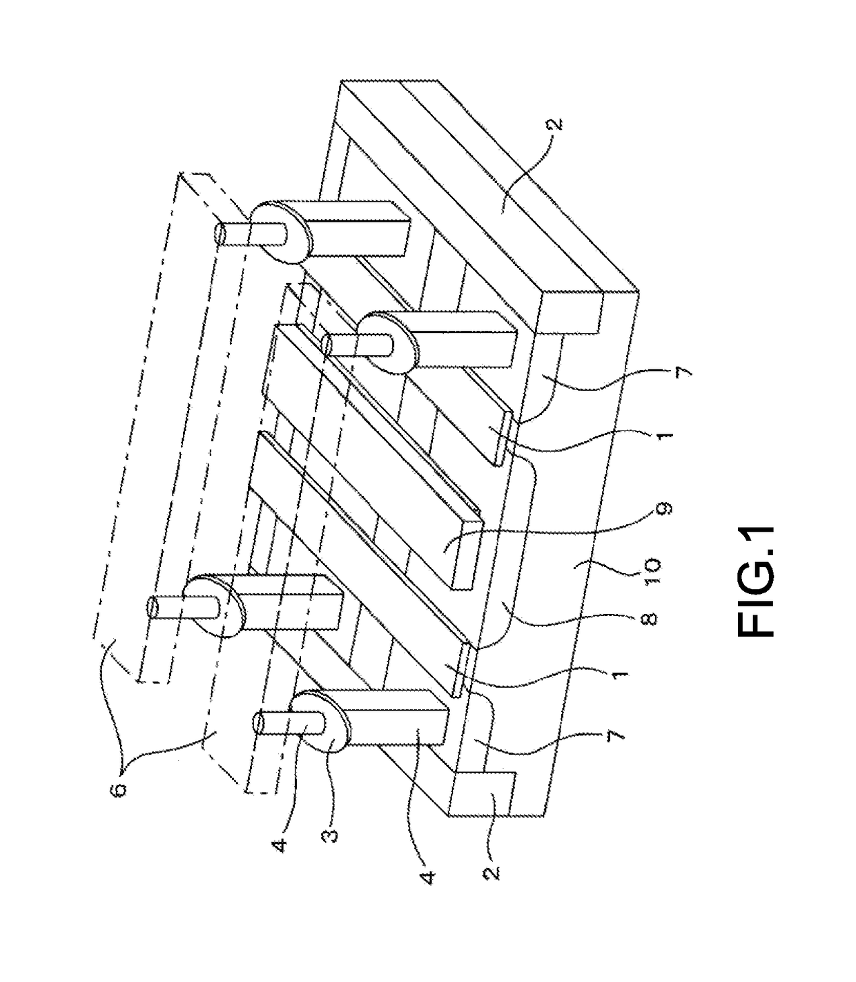
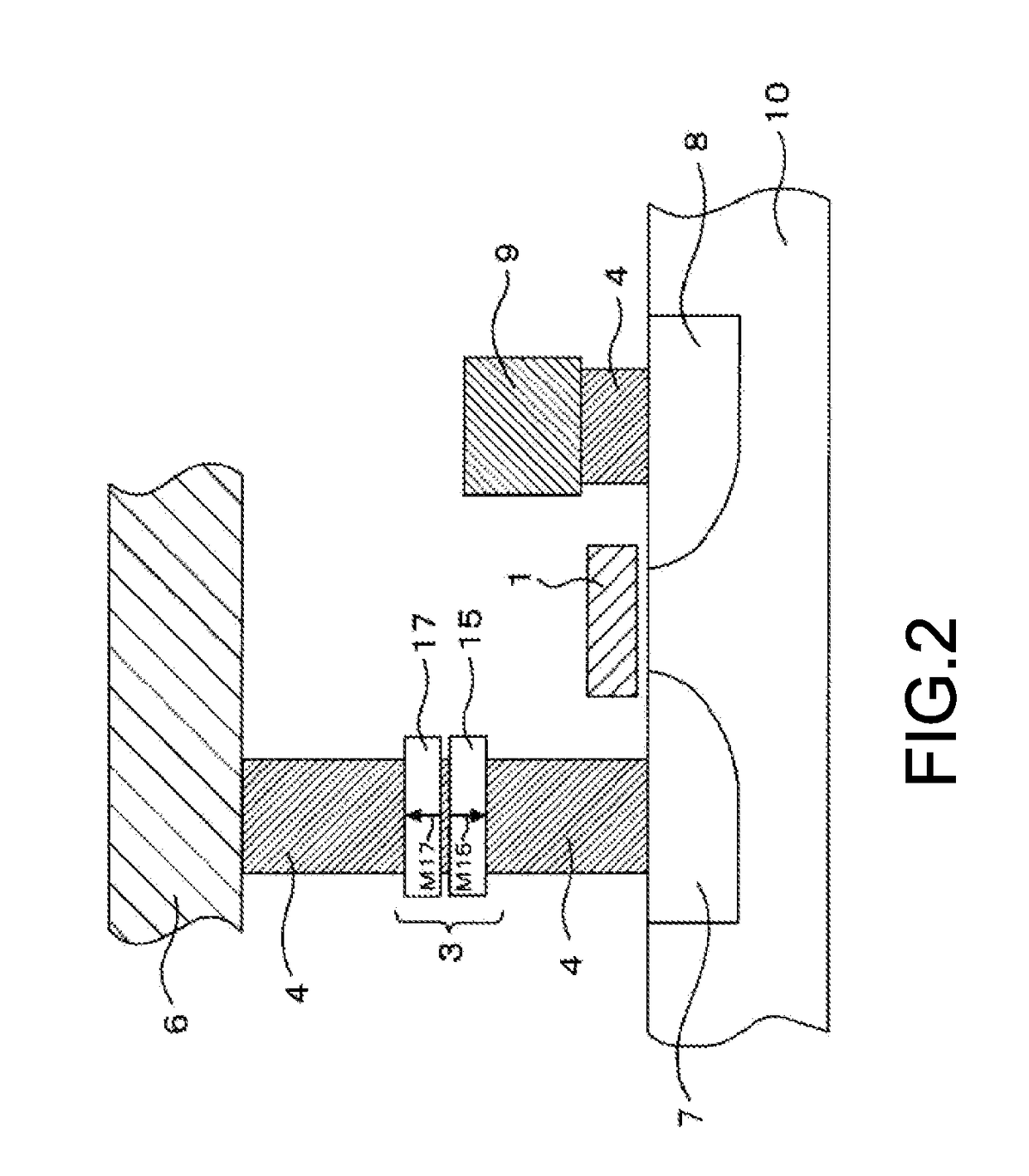
[0166]In an actual memory apparatus, as shown in FIG. 1, a semiconductor circuit for switching or the like is present in addition to the memory elements 3 and 20, but here, the examination was conducted on a wafer in which only a memory element is formed in order to check the magnetization inversion properties of the memory layer 17 adjacent to the cap layer 18.
[0167]As the sample of a...
experiment 1
[0182]This experiment was conducted to obtain the temperature change of perpendicular anisotropy of each sample described above.
[0183]The magnetization curve of the memory element is measured by magnetic kerr effect measurement and a Vibrating Sample Magnetometer to obtain the temperature change of the perpendicular anisotropy. For the measurement, not the element after being subject to minute processing but a bulk film portion having a size of about 8 mm×8 mm, which was specially provided on a wafer for magnetization curve evaluation, was used. Moreover, the measurement magnetic field was applied in the direction perpendicular to a film face.
[0184]FIG. 5 shows the obtained change of the perpendicular magnetic anisotropy of the samples 1 to 5 with respect to environment temperature. The temperature change of the magnetic anisotropy of the sample 2 and the samples 3 to 5 is larger than that of the sample 1. However, even in this case, there is no problem because the perpendicular mag...
experiment 2
[0194]In this experiment, in order to evaluate the writing properties of the memory element, the calculation of the value of the thermal stability index by the measurement of the magnetoresistance curve and the measurement of the inversion current value are performed in each sample described above.
[0195]A current with a pulse width of 10 μs to 100 ms was applied to the memory element, and the subsequent resistance value of the memory element was measured. Furthermore, the amount of currents applied to the memory element was changed, and the current value at which the direction of the magnetization of the memory layer of the memory element is inverted was obtained.
[0196]Moreover, the distribution of the coercive force obtained by measuring the magnetoresistance curve of the memory element a plurality of times corresponds to the index (Δ) of the holding properties (thermal stability) of the memory element. As the measured distribution of the coercive force is less, a higher A value is...
PUM
 Abstract
Description
Claims
Application Information
 - R&D
- Intellectual Property
- Life Sciences
- Materials
- Tech Scout
- Unparalleled Data Quality
- Higher Quality Content
- 60% Fewer Hallucinations
Browse by: Latest US Patents, China's latest patents, Technical Efficacy Thesaurus, Application Domain, Technology Topic, Popular Technical Reports.
© 2025 PatSnap. All rights reserved.Legal|Privacy policy|Modern Slavery Act Transparency Statement|Sitemap|About US| Contact US: help@patsnap.com


