

Vortex flowmeter, pressure sensor for a vortex flowmeter and method for producing such a pressure sensor
- Summary
- Abstract
- Description
- Claims
- Application Information
AI Technical Summary
Benefits of technology
Problems solved by technology
Method used
Image

Examples
Embodiment Construction
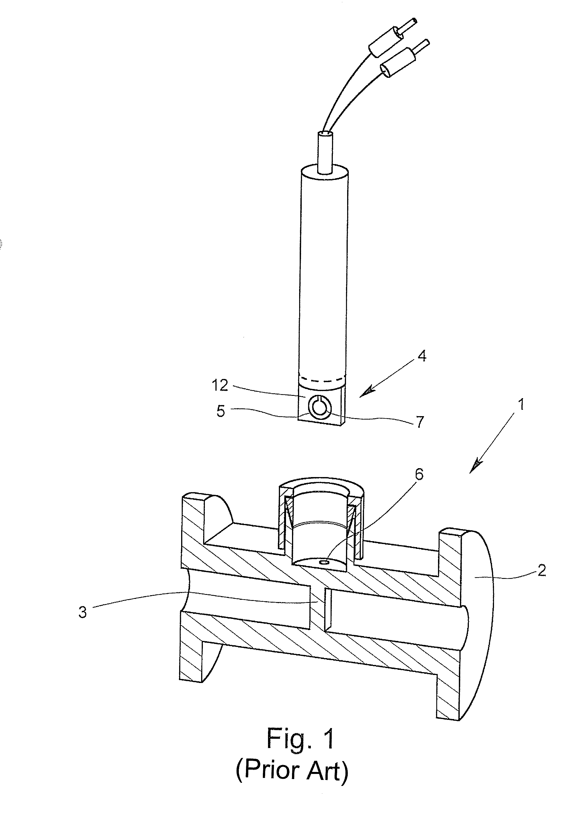
[0029]FIG. 1 is a sectional view of a vortex flowmeter 1 shown with a measuring tube 2 that can have a medium—not further shown—flowing through it and which has such a medium flowing through it during operation. A bluff body 3 is provided in the measuring tube 2, which creates vortices downstream in the medium when a medium is flowing through the measuring tube 2. The vortices strip away from the bluff body downstream and are carried away by the medium and form a vortex street. The frequency, at which the vortices strip away, is a measure for the velocity of flow within the measuring tube 2. With the exception of the nature of the pressure sensor 4, the structure shown in FIG. 1 is applicable to the present invention.
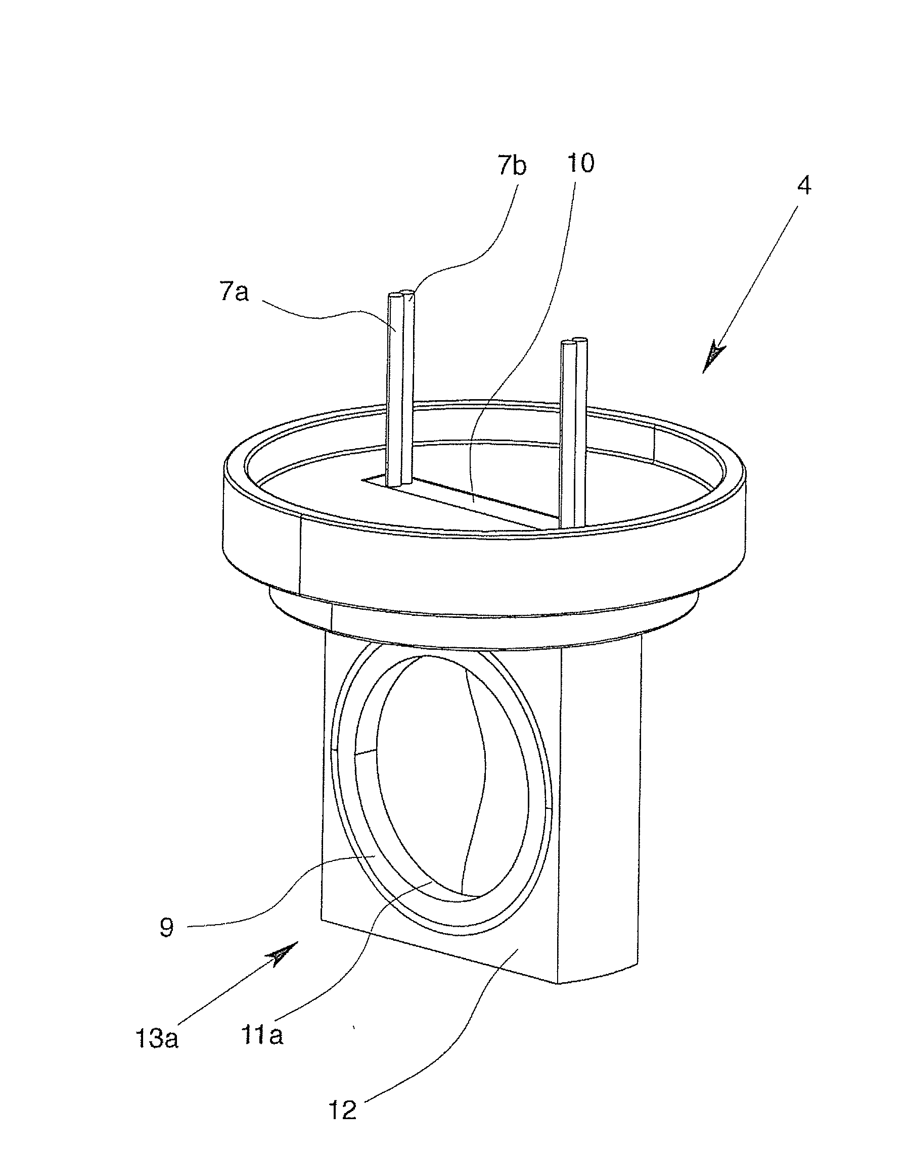
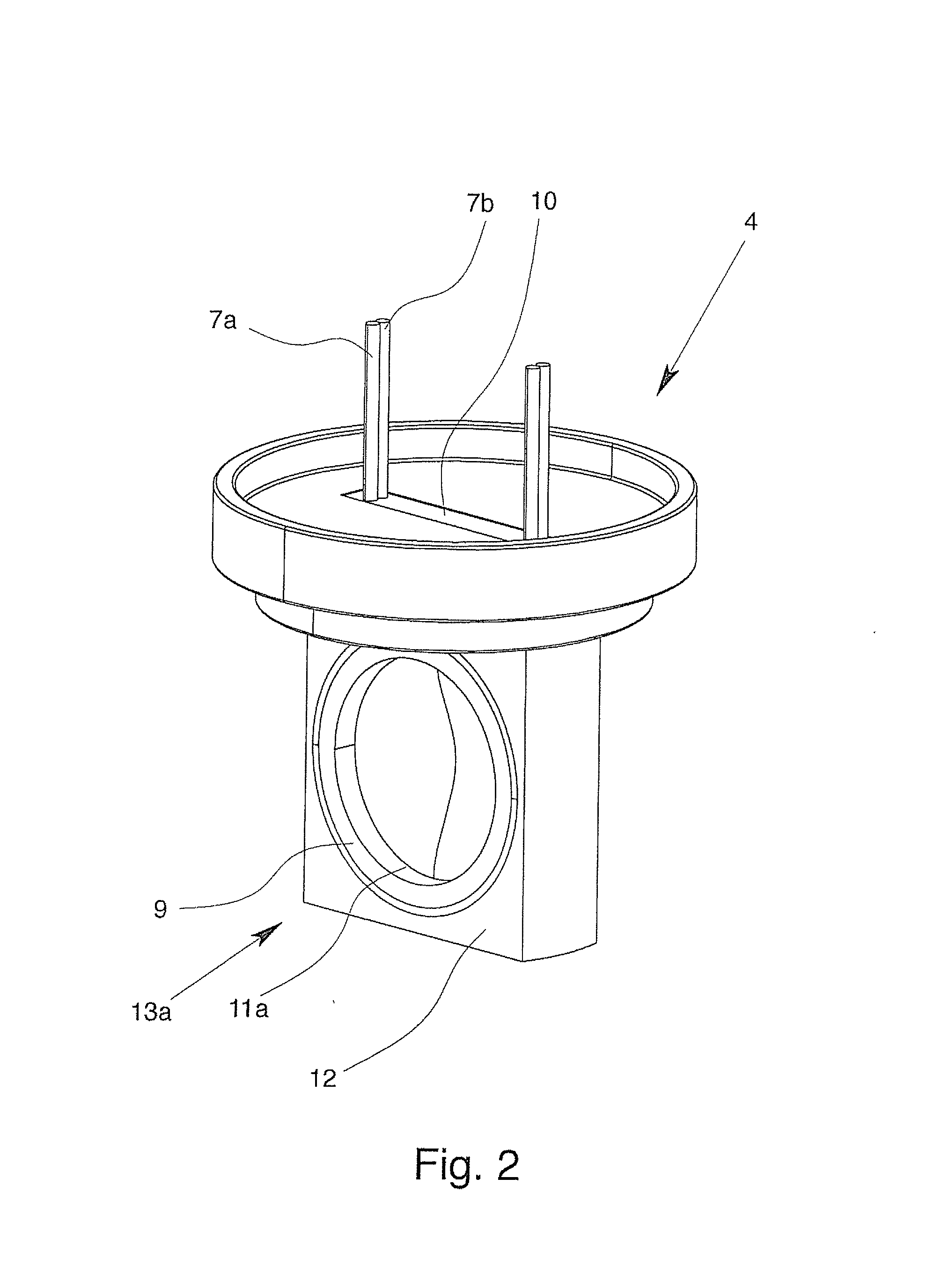
[0030]Furthermore, a pressure sensor 4 is provided in the effective range of the bluff body 3, wherein the pressure sensor 4 has a deflectable measuring diaphragm 5 and the deflection of the measuring diaphragm 5 can be used as a measurement for detecting the pressure i...
PUM
| Property | Measurement | Unit |
|---|---|---|
| Percent by mass | aaaaa | aaaaa |
| Thickness | aaaaa | aaaaa |
| Thickness | aaaaa | aaaaa |
Abstract
Description
Claims
Application Information