Method And System For A Multi-Core Fiber Connector

a fiber connector and multi-core technology, applied in the field of fiber optics, can solve the problems of cable bulk penalties, large power requirements, and complex structure, and achieve the effects of small improvement in reach, limited scalability, and limited scalability

Inactive Publication Date: 2013-02-21
CISCO TECH INC
View PDF14 Cites 47 Cited by
  • Summary
  • Abstract
  • Description
  • Claims
  • Application Information

AI Technical Summary

Benefits of technology

The technical effect of this patent is about creating a new type of fiber connector that can have multiple cores within it. This allows for better performance and reliability when connecting optical fibers together.

Problems solved by technology

The technical problem addressed in this patent text relates to the challenges faced when scaling data networks to meet increasing demand for high bandwidth. Copper data channels have limitations including signal attenuation and crosstalk which make it difficult to improve their performance without significant expense and effort. Optical communication offers an alternative solution that overcomes many of these issues, providing greater flexibility and scalability.

Method used


Image

  • Method And System For A Multi-Core Fiber Connector
  • Method And System For A Multi-Core Fiber Connector
  • Method And System For A Multi-Core Fiber Connector

Examples


Embodiment Construction

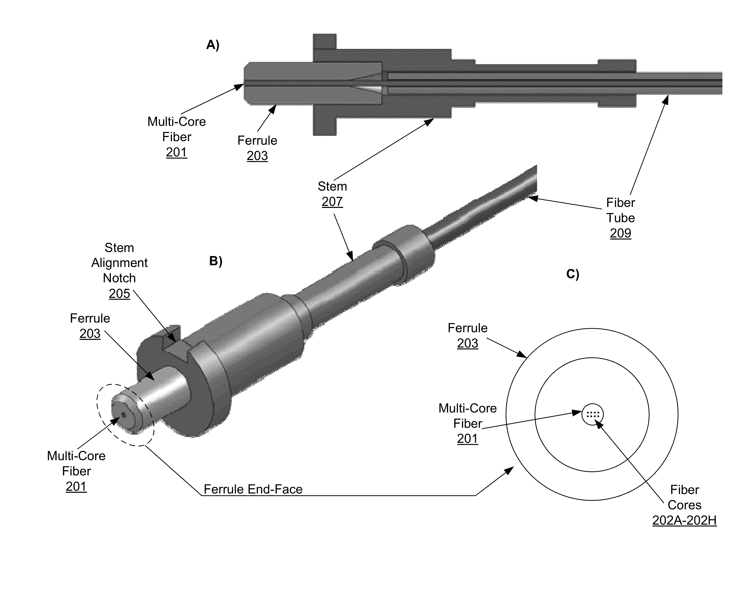
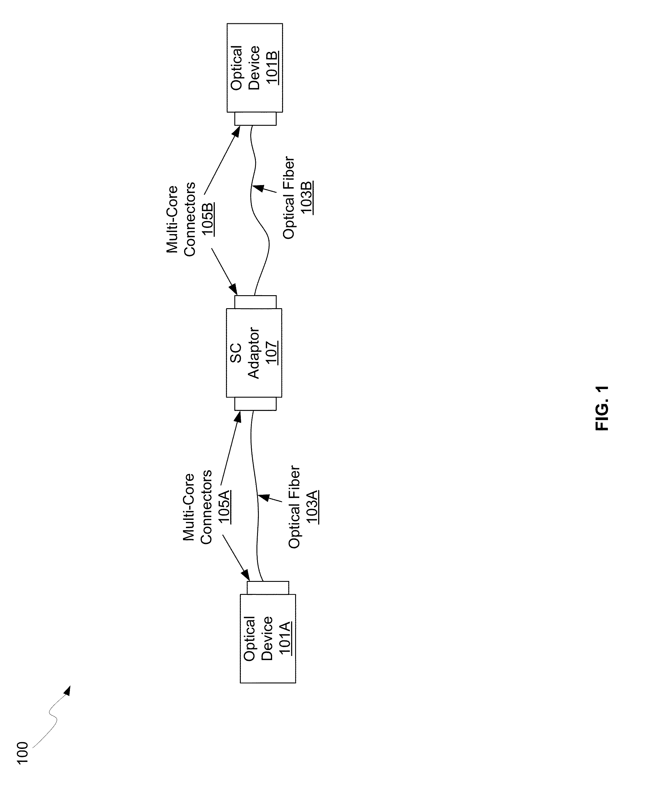
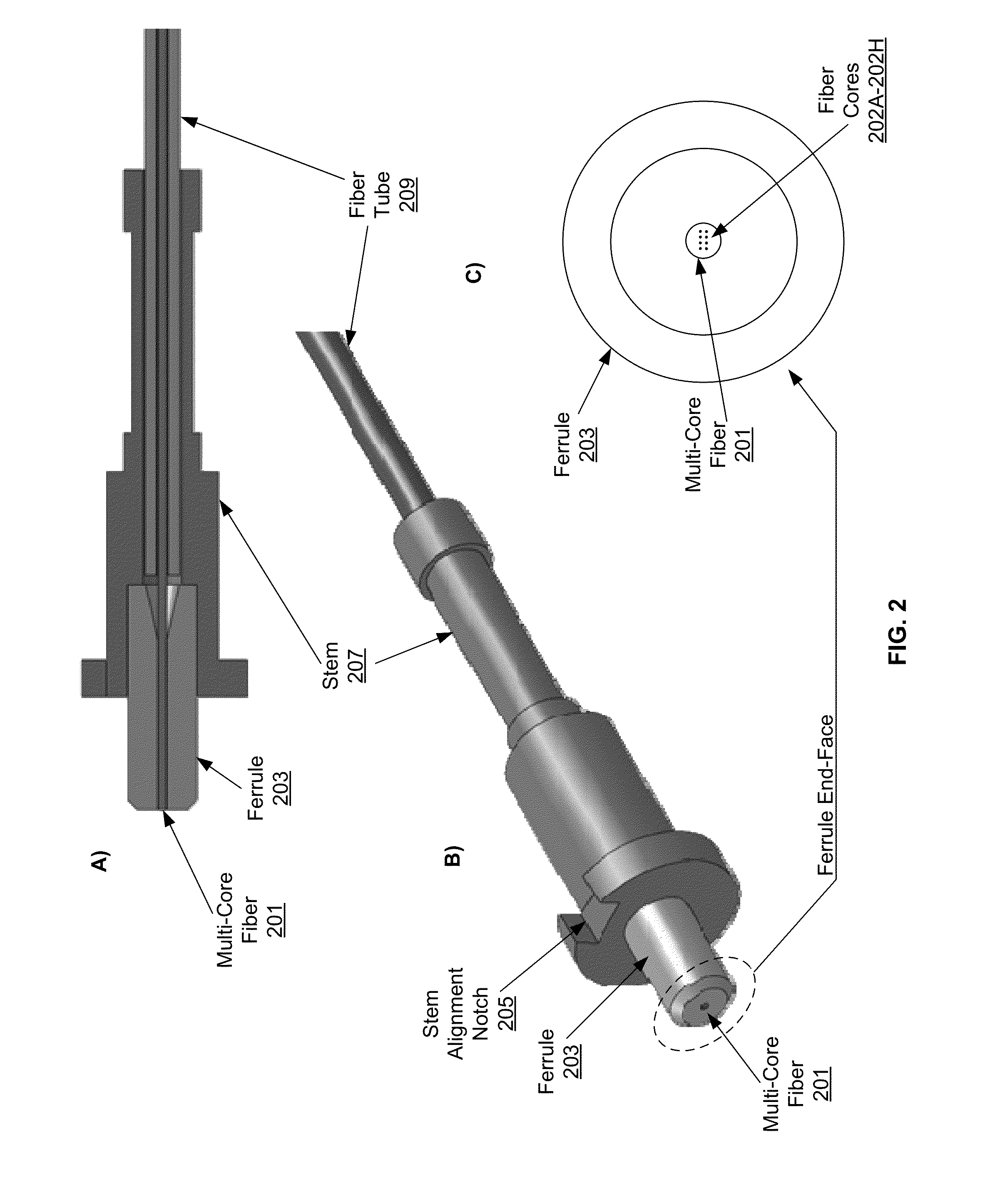
[0019]Certain aspects of the invention may be found in a method and system for a multi-core fiber connector. Exemplary aspects of the invention may comprise communicating optical signals in a fiber comprising a plurality of fiber cores and one or more connectors. The optical signals may be collimated utilizing a lens in the one or more connectors. The connectors may have dimensions to fit one or more of: standard connector (SC), fiber channel (FC), and / or Lucent connector (LC) connector assemblies. The lens may comprise a graded-index (GRIN) lens, an aspheric lens, or a ball lens. Each of the one or more connectors may comprise a ferrule assembly that encompasses an end of the optical fiber and is at least partially within a stem assembly. The ferrule assembly may comprise zirconia and the stem assembly may comprise stainless steel. The plurality of fiber cores may be aligned utilizing an alignment notch in the stem assembly. The lens may be fixed adjacent to the ferrule assembly ut...


PUM


Abstract

Methods and systems for a multi-core fiber connector are disclosed and may include communicating optical signals in a fiber comprising a multi-core. The connectors may comprise dimensions to fit one or more of: SC, LC, FC, or MU connectors. The optical signals may be collimated utilizing a lens in the connectors, and may comprise a graded-index (GRIN) lens or a ball lens. The connectors may comprise a ferrule assembly that encompasses an end of the optical fiber and is at least partially within a stem assembly. The ferrule assembly may comprise zirconia and the stem assembly may comprise stainless steel. The lens may be fixed adjacent to the ferrule assembly utilizing a stainless steel tube. The collimated optical signals may be communicated to a receiving lens that may focus the collimated optical signals onto a plurality of optical cores in a receiving optical fiber.

Description


Claims


Application Information

Patent Timeline
Owner CISCO TECH INC
Why Eureka
Try Eureka