Triggering light grid and method for determining the position of containers

a technology of triggering light and container position, which is applied in the direction of material analysis, measurement devices, instruments, etc., can solve the problems of limited method speed, limited machine performance, and limited measurement height and consequently specific measurement tasks

Inactive Publication Date: 2013-04-04
KRONES AG
View PDF13 Cites 10 Cited by
  • Summary
  • Abstract
  • Description
  • Claims
  • Application Information

AI Technical Summary

Problems solved by technology

Detrimental in this arrangement, however, is that it is limited to a specific measurement height and consequently to a specific measuring task and specific container type.
Detrimental in this method, however, is that a comparatively large number of image points must be evaluated, so that the speed of the method is limited as a result.
The containers must furthermore be a minimum distance apart from one another for the scanning, as a result of which the machine performance is additionally limited.
When there is a change in the product, adj

Method used


Image

  • Triggering light grid and method for determining the position of containers
  • Triggering light grid and method for determining the position of containers
  • Triggering light grid and method for determining the position of containers

Examples


Embodiment Construction

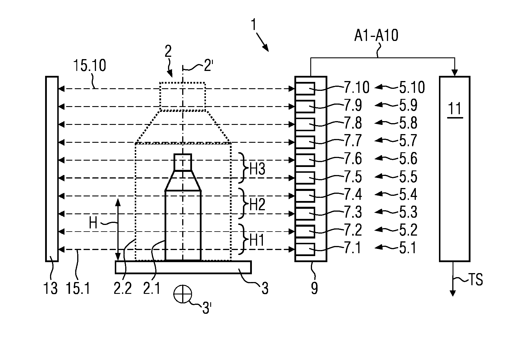
[0034]As can be seen in FIG. 1, the first embodiment 1 of the triggering light grid according to the present disclosure comprises, for acquiring the position P of containers 2 and / or for checking their alignment on a conveyance path 3, a plurality of light barriers 5.1 to 5.10 arranged at different height levels H with respect to the conveyance path 3, whereby each light barrier comprises light sources 7.1 to 7.10. These form the respective light transmitters of the light barriers 5.1 to 5.10 and are accommodated in a shared housing 9.

[0035]The light sources 7.1 to 7.10 can be activated individually and are connected to a triggering unit 11 for the generation of trigger signals TS, also called control signals in the following, on the basis of output signals A1 to A10 of the light barriers 5.1 to 5.10.

[0036]A continuous flow of containers 2 moves on the conveyance path 3, which is, for example, a conveyor belt or a rotation transporter, along the transport direction 3′, in the exampl...


PUM


Abstract

A triggering light grid and a method for registering the position of containers and/or for checking their alignment on a conveyance path. Due to the fact that a plurality of light barriers provided at different height levels with respect to the conveyance path and having light sources that can be activated separately of one another and a shared housing are provided, as is a triggering unit for the generation of control signals on the basis of output signals of the light barriers, different container types can be registered by reprogramming the triggering light grid without mechanical adjustment of the same.

Description

REFERENCE TO RELATED APPLICATIONS[0001]The present application claims the benefit of priority of German Application No. 102011083757.4, filed Sep. 29, 2011. The entire text of the priority application is incorporated herein by reference in its entirety.FIELD OF THE DISCLOSURE[0002]The disclosure relates to a triggering light grid and to a method for determining the position of containers.BACKGROUND DESCRIPTION OF THE RELATED ART[0003]To manufacture containers and / or to fill products into containers, these containers are normally transported to the individual treatment stations in a continuous product flow on transporters, such as conveyor belts, for example. In order to ascertain the presence and / or the position of containers on transporters, triggering light barriers, for example, can be used. When an object passes through the light barrier, a trigger signal is then generated with which a subsequent treatment step and / or a purposeful forwarding of the detected container can be actu...

Claims


Application Information

Patent Timeline
IPC IPC(8): G01B11/14
CPCG01V8/20G01B11/14G01N21/9036
Inventor PIANA, STEFANGUT, THORSTENDUNZINGER, BERNHARDSCHAFFER, HELMUT
Owner KRONES AG
Why Eureka
Try Eureka