Audio or video encoder, audio or video decoder and related methods for processing multi-channel audio or video signals using a variable prediction direction

Active Publication Date: 2013-05-16
FRAUNHOFER GESELLSCHAFT ZUR FOERDERUNG DER ANGEWANDTEN FORSCHUNG EV
View PDF20 Cites 73 Cited by
  • Summary
  • Abstract
  • Description
  • Claims
  • Application Information

AI Technical Summary

Benefits of technology

[0025]To increase audio or video quality, the same real-to-imaginary or imaginary-to-real converter which is applied on the decoder side is implemented on the encoder side as well, when the prediction residual signal is calcula

Problems solved by technology

In this concept, a combination of the left or first audio channel signal and the right or second audio channel signal is formed to obtain a mid or mono signal M. Additionally, a difference between the left or first channel signal and the right or second channel signal is formed to obtain the side signal S. This mid/side coding method results in a significant coding gain, when the left signal and the right signal are quite similar to each other, since the side signal will become quite small.
When such a situation occurs in a certain frequency band, then one would again deactivate mid/side coding due to the lack of coding gain.
This means that, in a rendering machine, care has to be taken to render multi-channel signals which accurately reflect the cues, but the waveforms are not of decisive importance.
This approach can be complex particularly in the case, when the decoder has to apply a decorrelation processing in order to artificially create stereo signals which are decorrelated from each other, although all these channels are derived from one and the same downmix channel.
Decorrelators for this purpose are, depending on their implementation, complex and may introduce artifacts particularly in the case of transient signal portions.
Additionally, in contrast to waveform coding, the parametric coding approach is a lossy coding approach which in

Method used


Image

  • Audio or video encoder, audio or video decoder and related methods for processing multi-channel audio or video signals using a variable prediction direction
  • Audio or video encoder, audio or video decoder and related methods for processing multi-channel audio or video signals using a variable prediction direction
  • Audio or video encoder, audio or video decoder and related methods for processing multi-channel audio or video signals using a variable prediction direction

Examples


Embodiment Construction

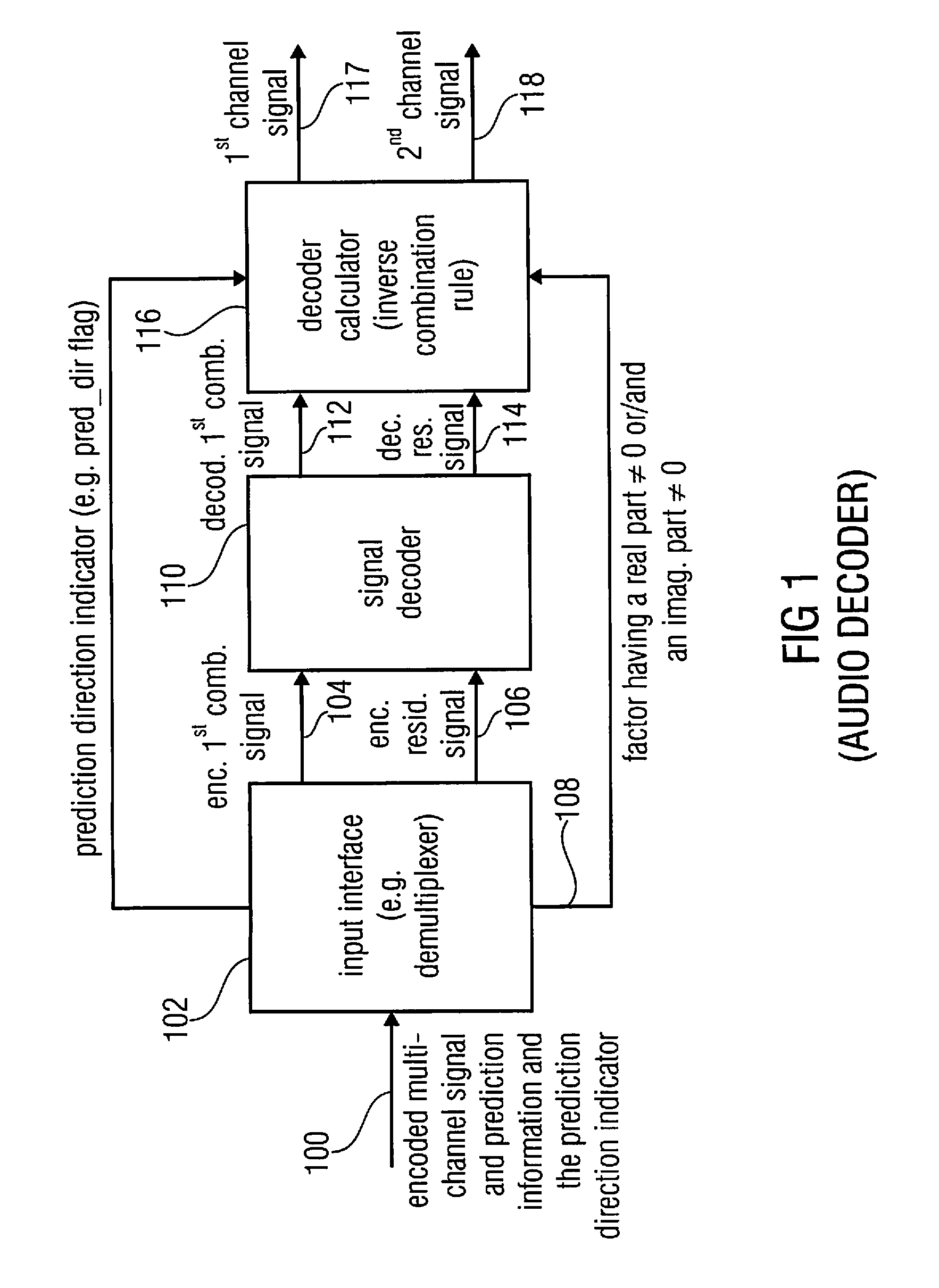
[0060]FIG. 1 illustrates an audio or video decoder for decoding an encoded multi-channel audio signal obtained at an input line 100. The encoded multi-channel audio signal comprises an encoded first combination signal generated using a combination rule for combining a first channel signal and a second channel signal representing the multi-channel audio signal, an encoded prediction residual signal and prediction information. The encoded multi-channel signal can be a data stream such as a bitstream which has the three components in a multiplexed form. Additional side information can be included in the encoded multi-channel signal on line 100. The signal is input into an input interface 102. The input interface 102 can be implemented as a data stream demultiplexer which outputs the encoded first combination signal on line 104, the encoded residual signal on line 106 and the prediction information on line 108. Advantageously, the prediction information is a factor having a real part no...


PUM


Abstract

An encoder/decoder is based on a combination of two audio or video channels to obtain a first combination signal as a mid-signal and a residual signal derivable using a predicted side signal derived from the mid-signal. A decoder uses the prediction residual signal, the first combination signal, a prediction direction indicator and prediction information to derive decoded first channel and second channel signals. A real-to-imaginary transform can be applied for estimating the imaginary part of the spectrum of the first combination signal. The prediction signal used in the derivation of the prediction residual signal, the real-valued first combination signal is multiplied by a real portion of the complex prediction information and the estimated imaginary part of the first combination signal is multiplied by an imaginary portion of the complex prediction information.

Description

CROSS-REFERENCE TO RELATED APPLICATIONS[0001]This application is a continuation of copending International Application No. PCT / EP2011 / 052354, filed Feb. 17, 2011, which is incorporated herein by reference in its entirety, and additionally claims priority from US Application No. 61 / 323,683, filed Apr. 13, 2010, which is also incorporated herein by reference in its entirety.[0002]The present invention is related to audio or video processing and, particularly, to multi-channel audio or video processing of a multi-channel signal having two or more channel signals.BACKGROUND OF THE INVENTION[0003]It is known in the field of multi-channel or stereo processing to apply the so-called mid / side stereo coding. In this concept, a combination of the left or first audio channel signal and the right or second audio channel signal is formed to obtain a mid or mono signal M. Additionally, a difference between the left or first channel signal and the right or second channel signal is formed to obtain...

Claims


Application Information

Patent Timeline
IPC IPC(8): H04N7/26G10L19/008G10L19/06
CPCG10L19/008H04N19/50H04N19/00569G10L19/06H04N19/105H04N19/156H04N19/154H04N19/146H04N19/70G10L19/00
Inventor ROBILLARD, JULIENNEUSINGER, MATTHIASHELMRICH, CHRISTIANHILPERT, JOHANNESRETTELBACH, NIKOLAUSDISCH, SASCHAEDLER, BERND
Owner FRAUNHOFER GESELLSCHAFT ZUR FOERDERUNG DER ANGEWANDTEN FORSCHUNG EV
Why Eureka
Try Eureka