
Motorcycle Helmet Mirror

a technology for motorcycle helmets and mirrors, which is applied in the field of motorcycle helmet mirrors, can solve the problems of unreliable peripheral vision, difficult to see unsteady image, and increase the number of motorcycle accidents

Inactive Publication Date: 2013-06-13
GARRELS ROGER D
View PDF10 Cites 11 Cited by
  • Summary
  • Abstract
  • Description
  • Claims
  • Application Information

AI Technical Summary

Benefits of technology

The motorcycle helmet assembly described in this patent includes a support arm that is attached to the shell of the helmet. The support arm has a mounting pad that is securely attached to the transparent face shield of the helmet using adhesive. The mounting pad has a groove that allows it to bend and conform to the curved shape of the face shield. This design allows the motorcyclist to see the image reflected by the mirror while wearing the helmet. The technical effect of this design is improved visibility and safety for motorcyclists.

Problems solved by technology

The technical problem addressed in this patent is the difficulty and safety risks involved in attaching traditional rear view mirrors to motorcycling equipment like helmets. Current methods involve either relying on peripheral vision or taking time to adjust the mirrors, making them inconvenient and potentially unsafe while driving. There has been a long history of trying various solutions, but none have fully met these requirements until now.

Method used


Image

  • Motorcycle Helmet Mirror
  • Motorcycle Helmet Mirror
  • Motorcycle Helmet Mirror

Examples


Embodiment Construction

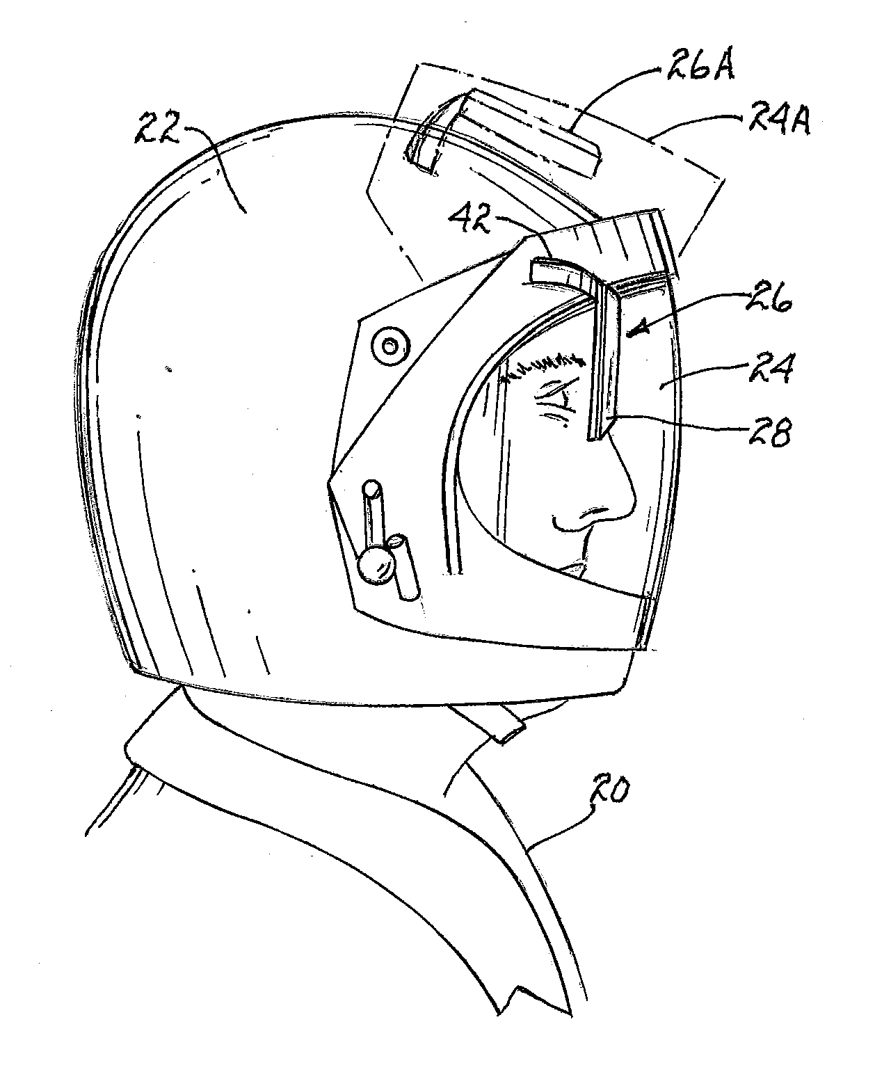
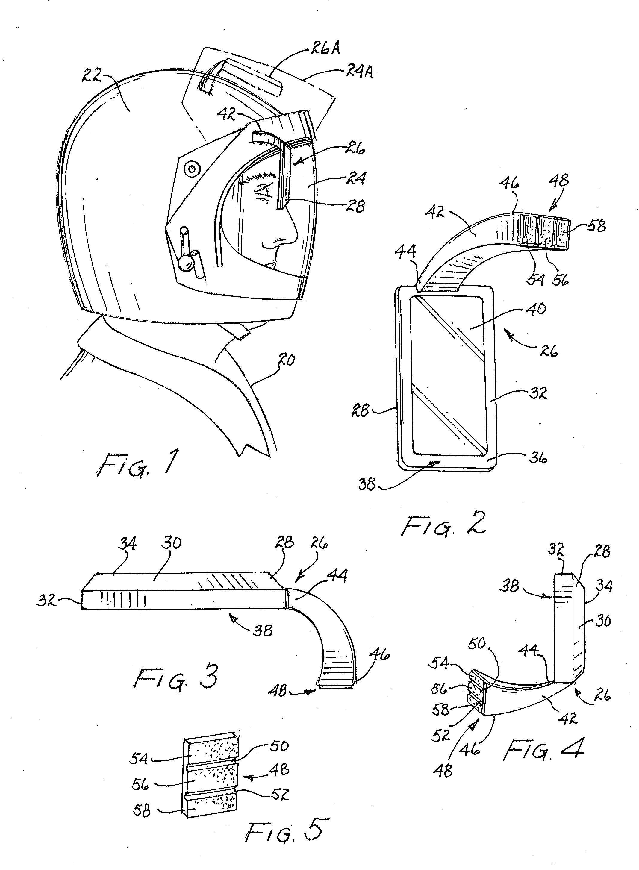
[0037]In FIG. 1, motorcycle rider 20 is shown wearing a conventional helmet 22. Helmet 22 extends about the head of motorcyclist 20, and a facial opening is formed therein for allowing a motorcyclist to observe the surroundings ahead. A transparent face shield 24 is secured to helmet 22 and extends over the aforementioned facial opening to shield the motorcyclist's face and eyes. Face shield 24 is pivotally connected to helmet 22, and may be flipped up to the position indicated by dashed lines 24A, when cyclist 20 has stopped or dismounted from a motorcycle. A mirror assembly 26, constructed in accordance with a preferred embodiment of the present invention, is shown secured to face shield 24; when face shield 24 is flipped up to its raised position 24A, mirror assembly 26A also flips up to a raised position.

[0038]Referring now to FIGS. 2-4, mirror assembly 26 includes an elongated shell 28 which has a central portion 30 surrounded by a peripheral portion 32. Peripheral portion 32 o...


PUM


Abstract

A mirror assembly for a motorcycle helmet includes an elongated shell having a partially-enclosed space for housing a mirror that is pivotally secured therein, and which reflects an image of the view behind the motorcyclist. The backing of the mirror and the inner surface of the shell are joined together by a ball and socket joint, permitting adjustment of the mirror orientation within the shell. A substantially rigid support arm is rigidly secured to the shell at one end, and includes a mounting pad at the opposite end. An adhesive layer secures the mounting pad to a portion of a motorcycle helmet or its associated face shield. The mounting pad may include one or more grooves to flex and conform to a curved surface.

Description


Claims


Application Information

Patent Timeline
Owner GARRELS ROGER D
Learn More