Anchor and method of installing anchor

Active Publication Date: 2013-08-08
ENUPATTO
View PDF8 Cites 10 Cited by
  • Summary
  • Abstract
  • Description
  • Claims
  • Application Information

AI Technical Summary

Benefits of technology

[0021]The anchor of the aforementioned structure or the method of installing the anchor achieves excellent working efficiency, allows the anchor to be installed such that the shaft such as a bolt or a

Problems solved by technology

The anchor of patent literature 1 is not suited for fixation to a ceiling structure.
So, if the ceiling structure is shaken strongly for example by an earthquake, the cone nut falls off the inside of the spreading sleeve, resulting in drop of the spreading sleeve integrated with the tip portion of the st

Method used


Image

  • Anchor and method of installing anchor
  • Anchor and method of installing anchor
  • Anchor and method of installing anchor

Examples


Example

[0031]A preferred embodiment of the present invention is described in detail below with reference to the drawings. Elements shared among the drawings to be referred to in the description below are represented by the same reference numerals, and are not described repeatedly.

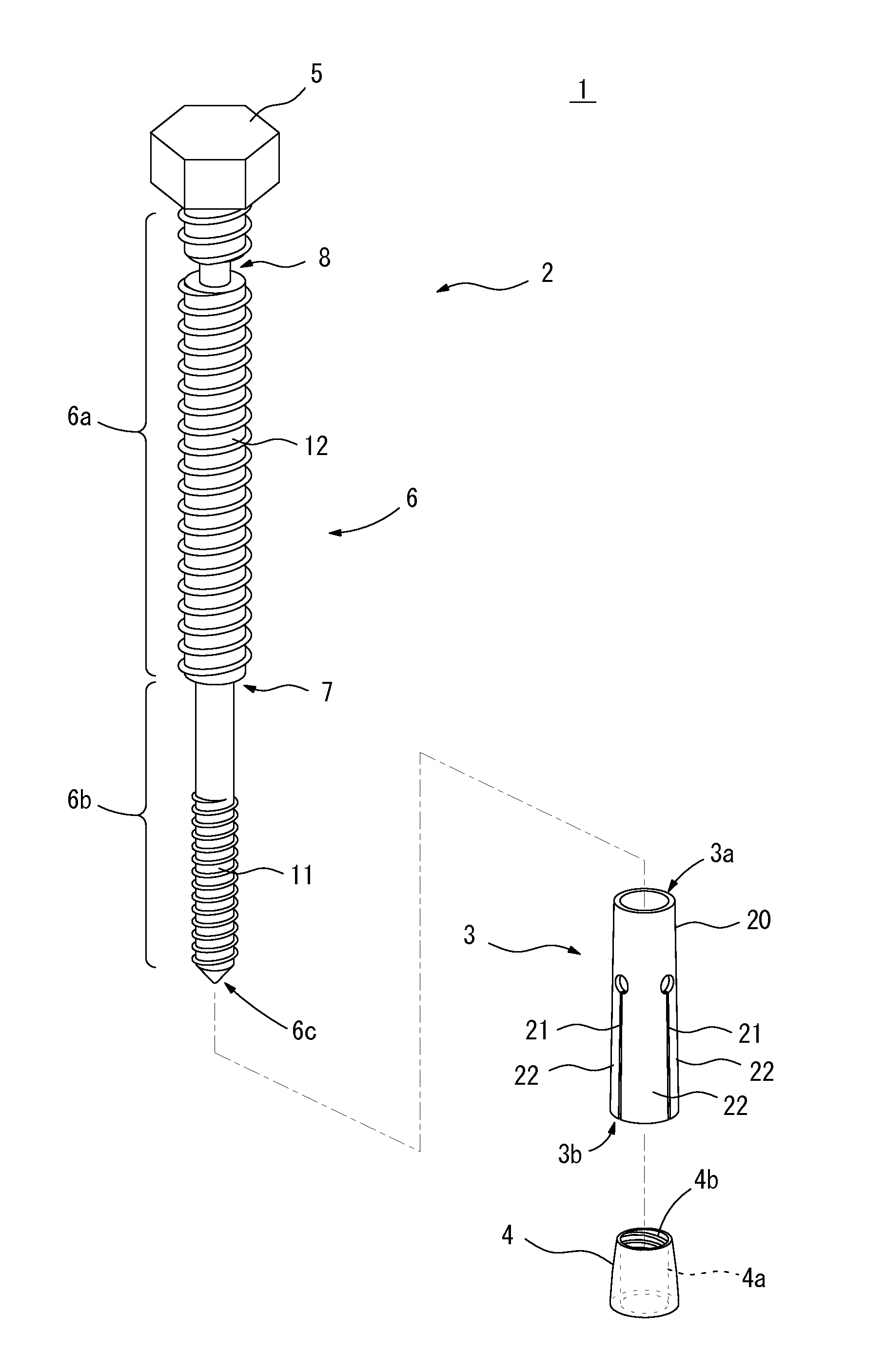
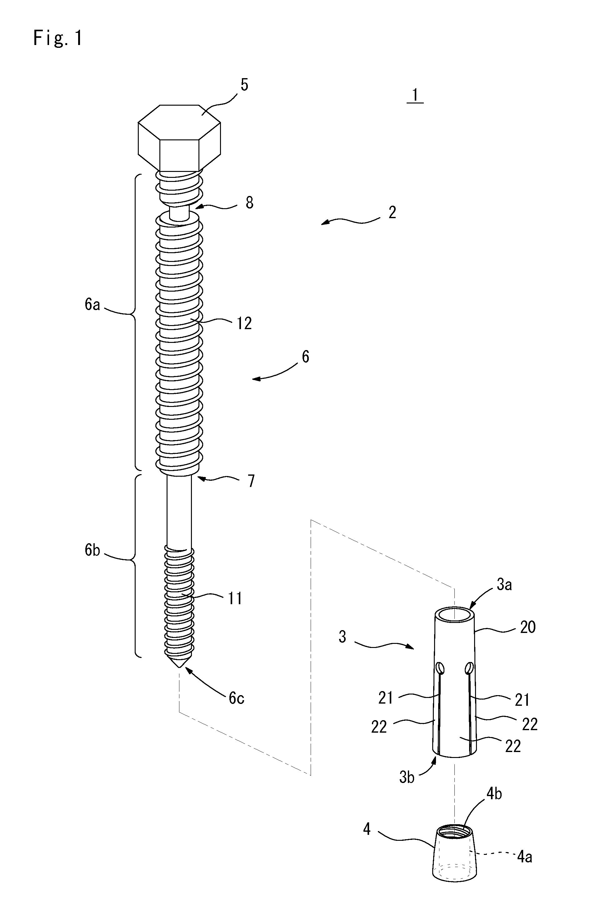
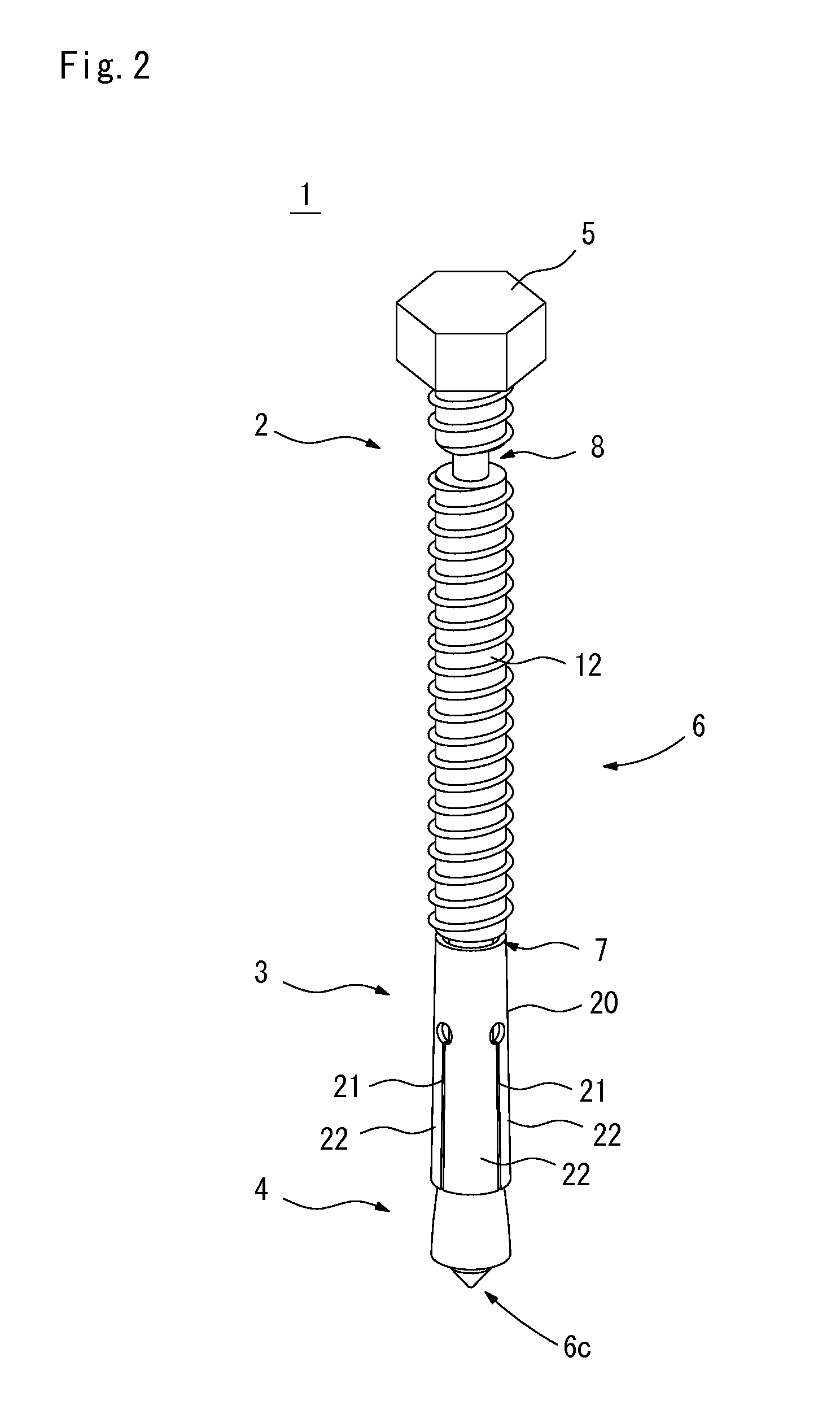
[0032]FIG. 1 is a perspective view of an anchor 1 of a preferred embodiment of the present invention with all parts of the anchor 1 separated. FIGS. 2 and 3 are a perspective view and a longitudinal sectional view respectively of the anchor 1 with all the parts of the anchor 1 assembled.

[0033]As shown in FIG. 1, the anchor 1 of the preferred embodiment is a metallic anchor composed of an anchor bolt 2, a spreading sleeve 3, and a cone nut 4. The anchor 1 is to be attached and fixed to various types of skeletons such as concrete buildings and structures, and is applicable to all of a ceiling structure, a wall surface, and a floor.

[0034]The anchor bolt 2 has a bolt head 5 and a shaft 6 coupled to each other. The bol...


PUM


Abstract

An anchor comprises an anchor bolt having a shaft and a bolt head, a spreading sleeve having spreading parts provided at a tip portion of a tubular body capable of being fitted on a tip portion of the shaft and a cone nut provided at its inner side a screw through hole to threadedly engage with the shaft. The shaft of the anchor bolt is composed of a thick shaft part connected to the bolt head, and a thin shaft part provided to be closer to the tip portion of the shaft. The thick shaft part is provided with a rupture portion reduced in diameter. The rupture portion is provided at a position spaced by a predetermined length from the step between the thick shaft part and the thin shaft part and ruptures if torque of a predetermined value acts on the bolt head.

Description

[0001]This application is based on the applications Nos. 2012-020474 and 2012-257321 filed in Japan, the contents of which are hereby incorporated by reference.BACKGROUND OF THE INVENTION[0002]1. Field of the Invention[0003]The present invention relates to an anchor to be attached to various types of skeletons such as concrete buildings and structures, and a method of installing the anchor.[0004]2. Background Art[0005]In order to attach hanging objects such as air conditioners, lighting fixtures, and various types of pipes to an existing ceiling structure of a concrete building, for example, anchors to support the hanging objects are fixed to the ceiling structure. These anchors may be fixed not only to a ceiling structure but also to a wall surface or a floor. Conventionally known anchors of this type are disclosed for example in Japanese Patent Applications Laid-Open Nos. 10-231583 (1998) (patent literature 1) and 10-110475 (1998) (patent literature 2).[0006]Referring for example ...

Claims


Application Information

Patent Timeline
IPC IPC(8): E21D21/00
CPCE21D21/008F16B31/021F16B13/066
Inventor IKUNO, MAKOTO
Owner ENUPATTO
Why Eureka
Try Eureka