Home network system with transmission error recovery

a technology of transmission error recovery and home network, applied in the field of home entertainment system, can solve the problems of retransmission problems, audio/video data packet loss in transmission, and inability to recover transmission errors, etc., and achieve the effect of avoiding over/underflow

a technology of transmission error recovery and home network, applied in the field of home entertainment system, can solve the problems of retransmission problems, audio/video data packet loss in transmission, and inability to recover transmission errors, etc., and achieve the effect of avoiding over/underflow

US20130205353A1Active Publication Date: 2013-08-08SONY ELECTRONICS INC +1

Image

  • Home network system with transmission error recovery
  • Home network system with transmission error recovery
  • Home network system with transmission error recovery

Examples


Embodiment Construction

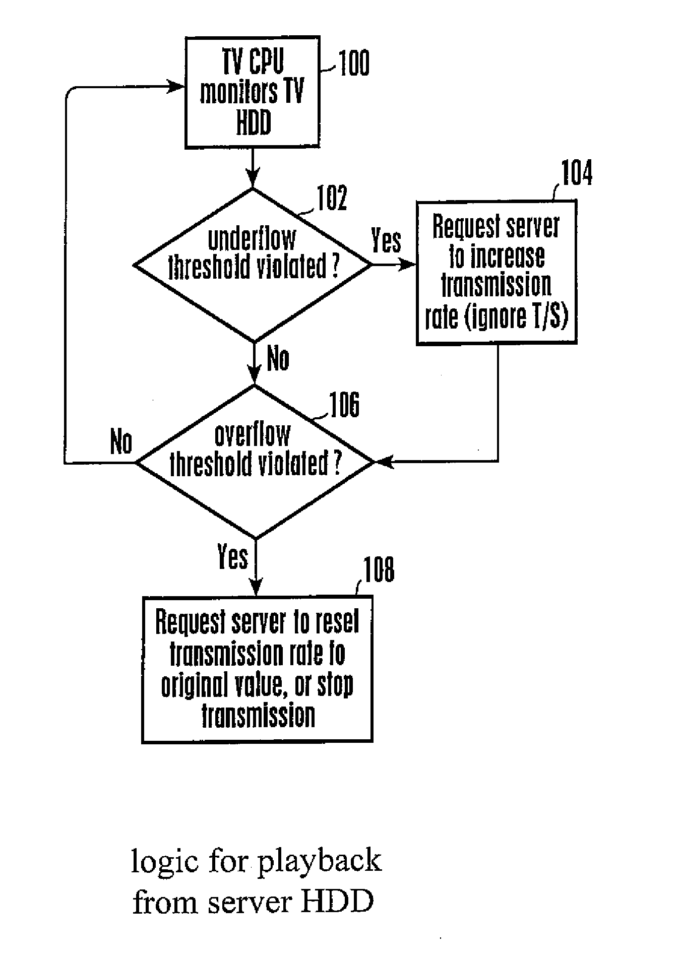
[0017]In the preferred non-limiting embodiment shown, the processors described herein may access one or more software or hardware elements to undertake the present logic. The flow charts herein illustrate the structure of the logic modules of the present invention as embodied in computer program software, in logic flow chart format, it being understood that the logic could also be represented using a state diagram or other convention. Those skilled in the art will appreciate that the flow charts illustrate the structures of logic elements, such as computer program code elements or electronic logic circuits, that function according to this invention. Manifestly, the invention is practiced in its essential embodiment by a machine component that renders the logic elements in a form that instructs a digital processing apparatus (that is, a computer or microprocessor) to perform a sequence of function steps corresponding to those shown. Internal logic could be as simple as a state machin...


PUM


Abstract

A client TV in a home entertainment network receives and buffers an audio / video stream from a server, before playing the stream. In the case of buffer underflow, the client TV requests the server to raise the transmission rate. If this causes an ensuing buffer overflow, the client TV requests the server to reset the transmission rate or stop transmitting altogether for a short time.

Description

RELATED APPLICATIONS[0001]This application claims priority from U.S. provisional patent application Ser. No. 60 / 591,455, filed Jul. 27, 2004.BACKGROUND OF THE INVENTION[0002]1. Field of the Invention[0003]The present invention relates generally to home entertainment systems.[0004]2. Description of the Related Art[0005]Home entertainment systems have been provided that can include a set-top box media server that communicates with various components in the home, e.g., TVs, laptop computers, and custom display devices. Home network communication technologies (e.g., 802.11. wireless, UWB (Ultra Wide Band), PLC (Power Line Communication), etc.) are widely used as their costs decrease.[0006]As critically recognized herein, wireless home networks are not as reliable as wired and dedicated networks such as Ethernet. Consequently, audio / video data packets frequently can be lost (“dropped”) in transmission. When a transmission is not time critical, retransmission of a dropped packet is not a ...

Claims


Application Information

Patent Timeline
08 Aug 2013
Publication
US20130205353A1
IPC
H04N21/24; H04L47/30; H04N21/6373
CPC
H04L12/2803; H04L12/2827; H04L47/10; H04L47/18; H04L47/263; H04L65/80; H04L2012/2843; H04L2012/2849
Inventors
IWAMURA, RYUICHI