Loudspeaker rigging system having upwardly extending connecting links

Active Publication Date: 2013-08-15
MEYER SOUND LABORATORIES
View PDF3 Cites 14 Cited by
  • Summary
  • Abstract
  • Description
  • Claims
  • Application Information

AI Technical Summary

Benefits of technology

The patent describes a new way to rig a stack of loudspeakers using special links that extend upward. This system allows for easy adjustment of the angle between each pair of speakers, and the frames can be locked in position quickly and easily using pins. This results in a more efficient and effective rigging system for loudspeakers.

Problems solved by technology

This can not only time be consuming, but becomes progressively more difficult as the number and added weight of rigged loudspeakers in a stack of loudspeakers increases.
The increasingly heavy stack of loudspeakers can bounce when lifted by a rigging hoist making it difficult for the pin holes in the side frames to align with the pin holes in the links and increasing the potential for physical injury to the equipment and to riggers.

Method used


Image

  • Loudspeaker rigging system having upwardly extending connecting links
  • Loudspeaker rigging system having upwardly extending connecting links
  • Loudspeaker rigging system having upwardly extending connecting links

Examples


Embodiment Construction

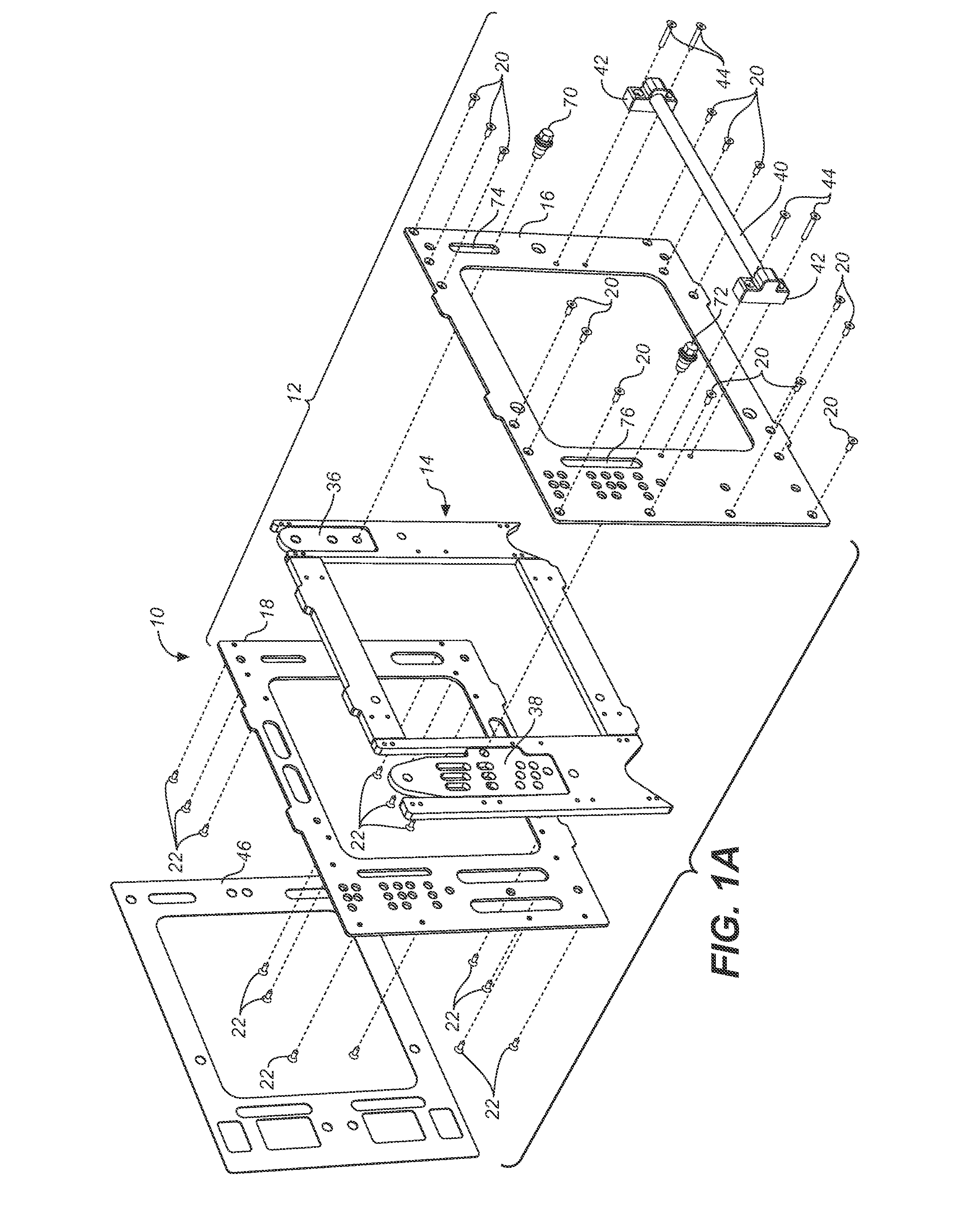
[0009]FIG. 1A is an exploded upper perspective view of a loudspeaker rigging system having upwardly extending connecting links.

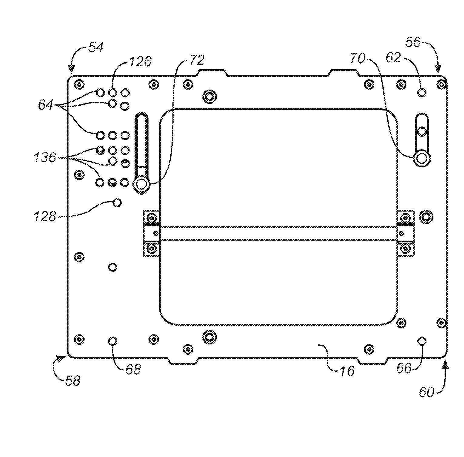
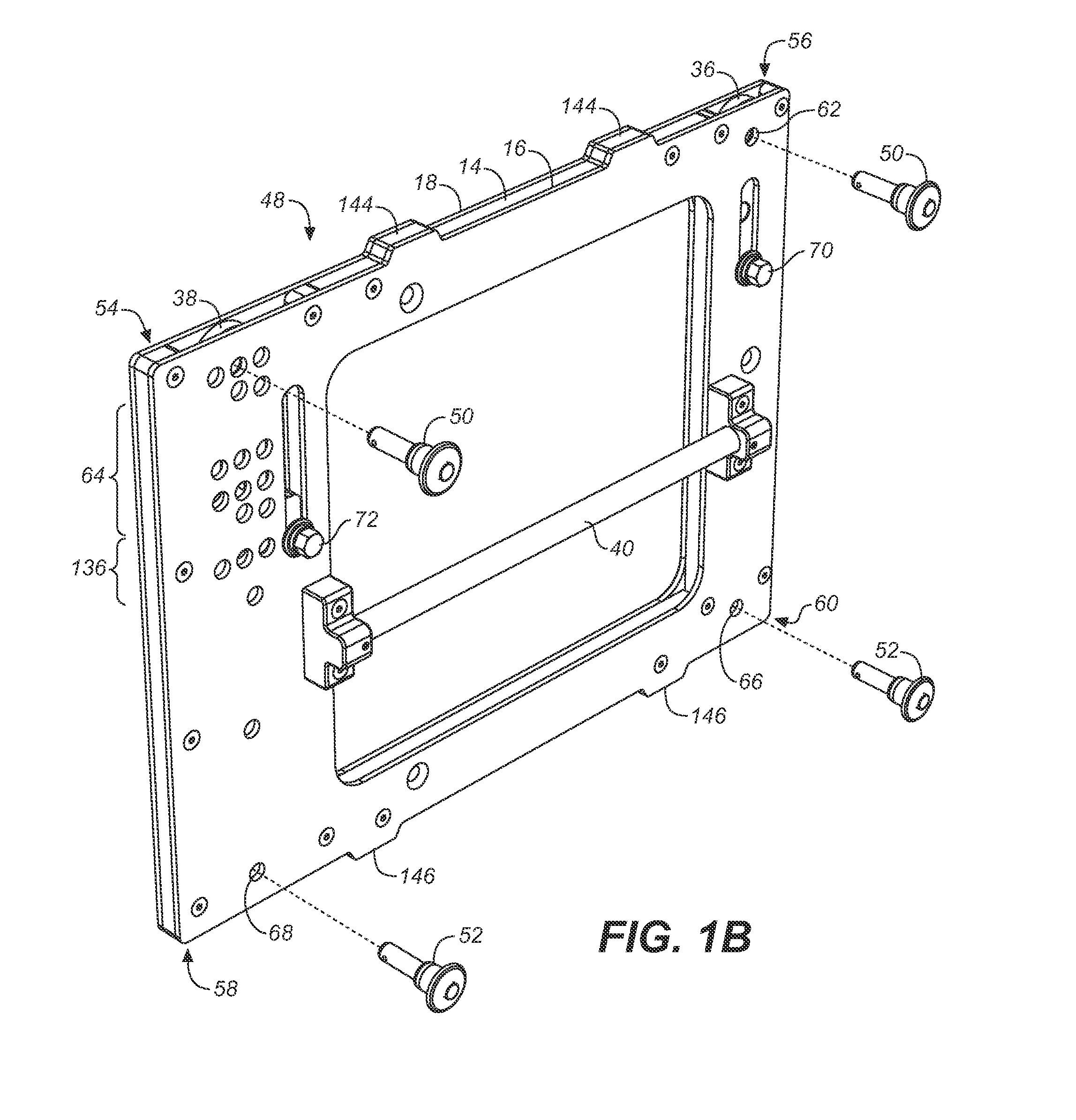
[0010]FIG. 1B is an upper left perspective view of the frame structure of the loudspeaker rigging system of FIG. 1A.

[0011]FIG. 2 is an elevation view of the center core assembly of the frame structure shown in FIG. 1B.

[0012]FIG. 3 is an elevation view showing the frame structure of the loudspeaker rigging system of FIG. 1.

[0013]FIG. 4A is an elevation view similar to FIG. 3 showing the frame structure of the loudspeaker rigging system but with the front side plate removed.

[0014]FIG. 4B is close-up elevation view similar to FIG. 4A showing upward movement of the connecting links.

[0015]FIG. 4C is an elevation view similar to FIG. 4A showing the frame structures of a pair of vertically adjacent loudspeakers with the connecting links upwardly deployed.

[0016]FIG. 4D is an elevation view similar to FIG. 4B showing movement of the splay adjustment link to one of a ...


PUM


Abstract

A loudspeaker rigging system having upwardly extending connecting links comprises splay adjustment and pivot links slidingly disposed in splay adjustment and pivot link stowing channels in a frame structure for the sides of a loudspeaker in a stack of loudspeakers, the splay adjustment and pivot links upwardly movable from stowed to linking positions, in the linking position the splay adjustment and pivot links linkable with locking pin holes in the bottom of the frame structure of a superjacent loudspeaker, the splay adjustment link having a plurality of splay angle slots of various lengths, the splay angle slots aligned with a plurality of splay angle selection pin holes in the frame structure, such that upon insertion of a linking pin in a selected splay angle selection pin hole and corresponding aligned splay angle slot the splay angle link may be raised upward to a selected splay angle.

Description

CROSS-REFERENCE TO RELATED APPLICATIONS[0001]This application claims the benefit of U.S. Provisional Application No. 61 / 524,217, filed Aug. 16, 2011.BACKGROUND[0002]1. Field of the Invention[0003]The present invention relates to loudspeaker rigging systems and more particularly to rigging hardware for suspending a stacked array of loudspeakers of a sound reinforcement system at a predetermined location relative to an audience. The present invention has particular application in rigging a stacked array of loudspeakers wherein a vertical splay between loudspeakers is desired to achieve a desired coverage and acoustic performance.[0004]2. Description of Related Art[0005]Sound systems for large venues typically involve the suspension or “flying” of stacks of loudspeakers in vertical arrays to achieve a desired acoustic output and coverage for a large audience. Such vertical stacks of loudspeakers are typically suspended and held together by rigging systems which may be attached to riggi...

Claims


Application Information

Patent Timeline
IPC IPC(8): H04R1/02
CPCH04R1/026H04R2201/025H04R2201/401H04R27/00H04R1/403H04R1/02
Inventor MCGHEE, JOHNRUBIO, ALEJANDRO GARCIAESPINOSA, PABLO
Owner MEYER SOUND LABORATORIES
Why Eureka
Try Eureka