Detection of Raindrops on a Pane by Means of a Camera and Lighting

Active Publication Date: 2013-09-12
CONTI TEMIC MICROELECTRONIC GMBH
View PDF9 Cites 31 Cited by
  • Summary
  • Abstract
  • Description
  • Claims
  • Application Information

AI Technical Summary

Benefits of technology

[0031]In an advantageous use of visible light as lighting it must be ensured that road users are not disturbed by the lighting.
[0032]For this purpose, it is proposed to use a short visible light pulse, adapted by the intensity of the external brightness. This would require only a short exposure time and image recording time for the rain sensor image, what in turn has little influence on the driver assistance function. Such a light pulse would be seen during daylight only when looking directly at th

Problems solved by technology

A disadvantage of this idea is the fact that an additional optical element is introduced, whose edge causes serious disturbances both in the beam path for the rain sensor area of the image chip as well as in the region for the driver assistance functions in the vicinity of the edge.
In particular for implementations with small dimensions, the focus conditions for the driver assistance and the rain sensor area are strongly different, what must be compensated by an increased thickness of the optical element, thus leading to increased disturbances and a broad, non-usable region on the image chip around the edge.
Another disadvant

Method used


Image

  • Detection of Raindrops on a Pane by Means of a Camera and Lighting
  • Detection of Raindrops on a Pane by Means of a Camera and Lighting
  • Detection of Raindrops on a Pane by Means of a Camera and Lighting

Examples


Embodiment Construction

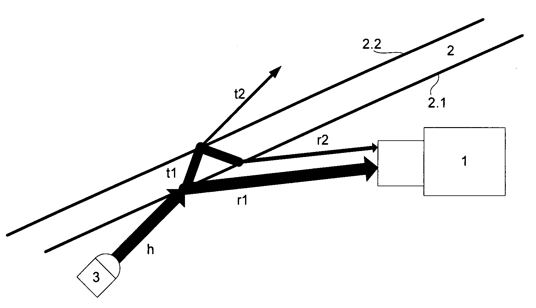
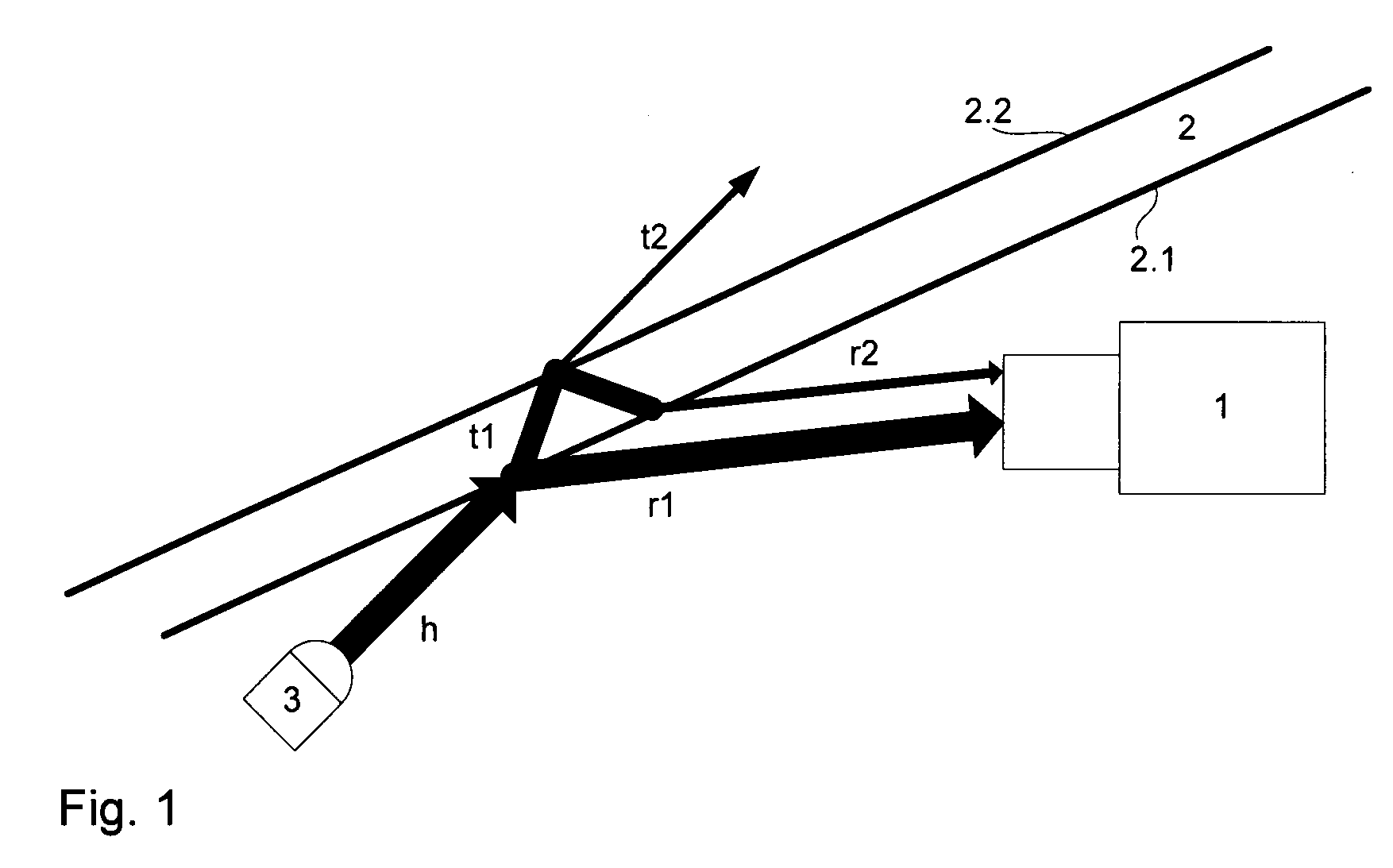
[0047]FIG. 1 illustrates the functional principle of a first form of embodiment of the invention. The presented rain detection is based on a camera (1) focused onto the far range and a lighting (3), which in contrast to the large-scale lighting from U.S. Pat. No. 7,259,367 B2 uses one or more focused beams (h).

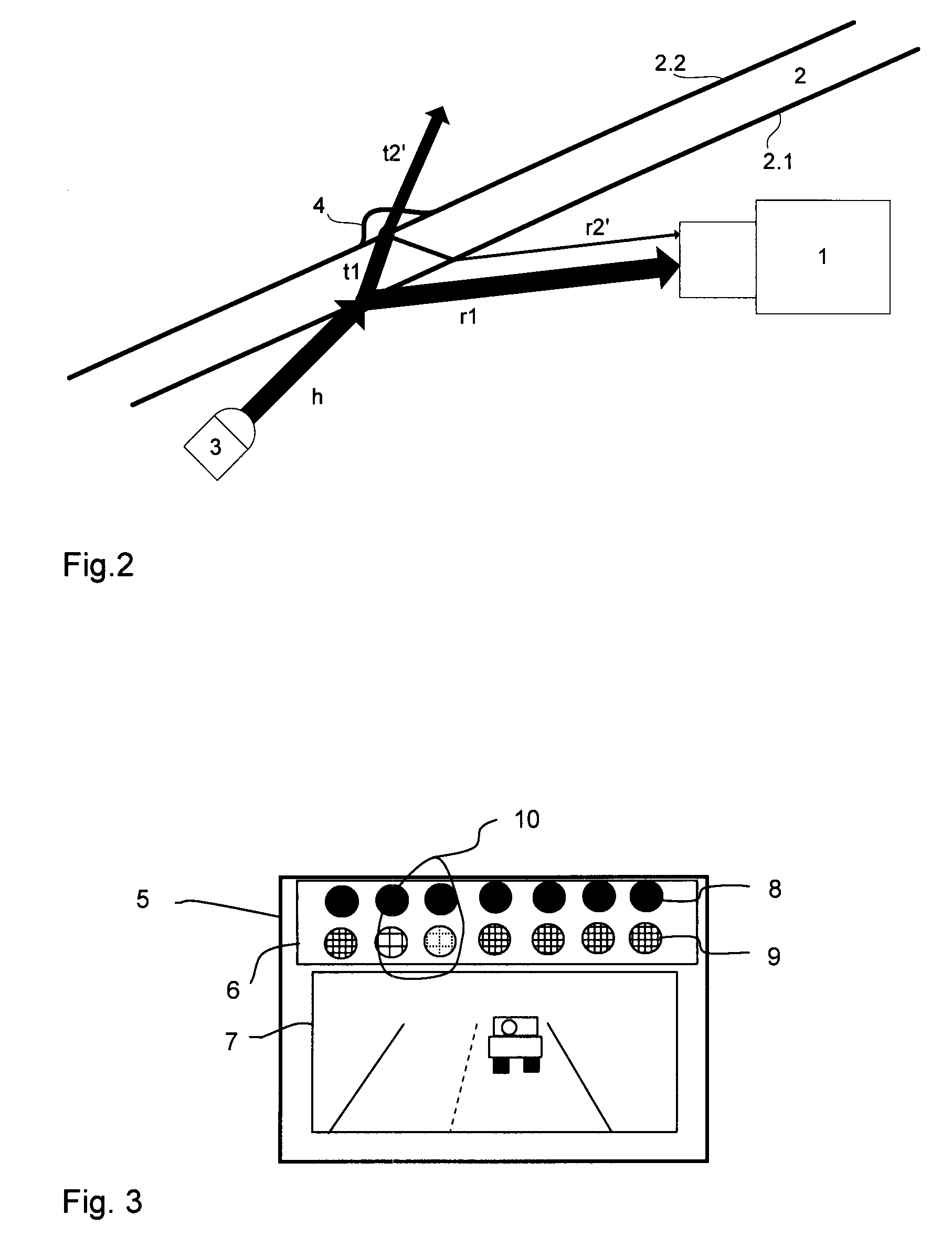
[0048]A light beam (h) generated by a lighting source (3) is directed towards the pane (2) such that the beams reflected from the inner (2.1) and outer face (2.2) of the pane impinge as two spatially separated beams (rl, r2) on the objective or the camera (1). Due to the focussing on the far range, the boundary of the beam bundle is imaged only blurred on the image chip (5). But both beams (r1, r2) are sufficiently separated and their respective light quantity can be measured with the image sensor (5).

[0049]In this form of embodiment, the main beam (h) of the lighting source (3) is used, therefore, the light of the lighting source can be preferably focused. The portion (r1) re...


PUM


Abstract

The invention relates to a device or a method for detecting rain (4), said device or method comprising a camera (1) and a lighting source (3). The camera (1) is disposed behind a pane (2), in particular in the interior of a vehicle behind a windscreen, and focused onto a far range that lies in front of the pane (2). The lighting source (3) for generating at least one light beam (h; n) that is directed at the pane (2) directs the at least one light beam (h; n) towards the pane (2) such that at least one beam (r2; r2′) that is reflected from the outer face (2.2) of the pane impinges on the camera (1).
The light quantity of the at least one beam (r2; r2′) that impinges on the camera (1) can be measured by the camera (1).

Description

FIELD OF THE INVENTION[0001]The invention relates to a device and a method for detecting raindrops on a pane by means of a lighting source and a camera.BACKGROUND OF THE INVENTION[0002]In WO2010 / 072198 A1 rain detection is described with the aid of a camera, which is used for automotive driver assistance functions. For rain detection bifocal optics are used, which form a sharp image of a portion of the windscreen onto a portion of the image chip or image sensor of the camera.[0003]A disadvantage of this idea is the fact that an additional optical element is introduced, whose edge causes serious disturbances both in the beam path for the rain sensor area of the image chip as well as in the region for the driver assistance functions in the vicinity of the edge. In particular for implementations with small dimensions, the focus conditions for the driver assistance and the rain sensor area are strongly different, what must be compensated by an increased thickness of the optical element,...

Claims


Application Information

Patent Timeline
IPC IPC(8): G01N21/55
CPCB60S1/0844G01N21/55G01N2021/435G01N21/552G06V20/56B60S1/08
Inventor KROEKEL, DIETERCHIVUKULA, RADHAKRISHNA
Owner CONTI TEMIC MICROELECTRONIC GMBH
Why Eureka
Try Eureka