Liquid cooling system

Active Publication Date: 2006-02-23
RITTALWERK RUDOLF LOH GMBH & CO KG
View PDF7 Cites 14 Cited by
  • Summary
  • Abstract
  • Description
  • Claims
  • Application Information

AI Technical Summary

Benefits of technology

[0006] One object of this invention is to provide a liquid cooling system of the type mentioned above but where cooling can be dependably provided, in particular in

Problems solved by technology

However, if a rack or a switchgear cabinet has a multitude of electronic component groups with high computer output, very large amounts

Method used


Image

  • Liquid cooling system
  • Liquid cooling system

Examples


Embodiment Construction

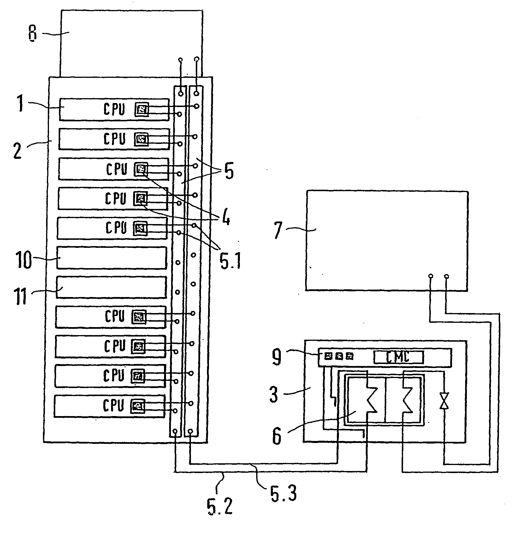
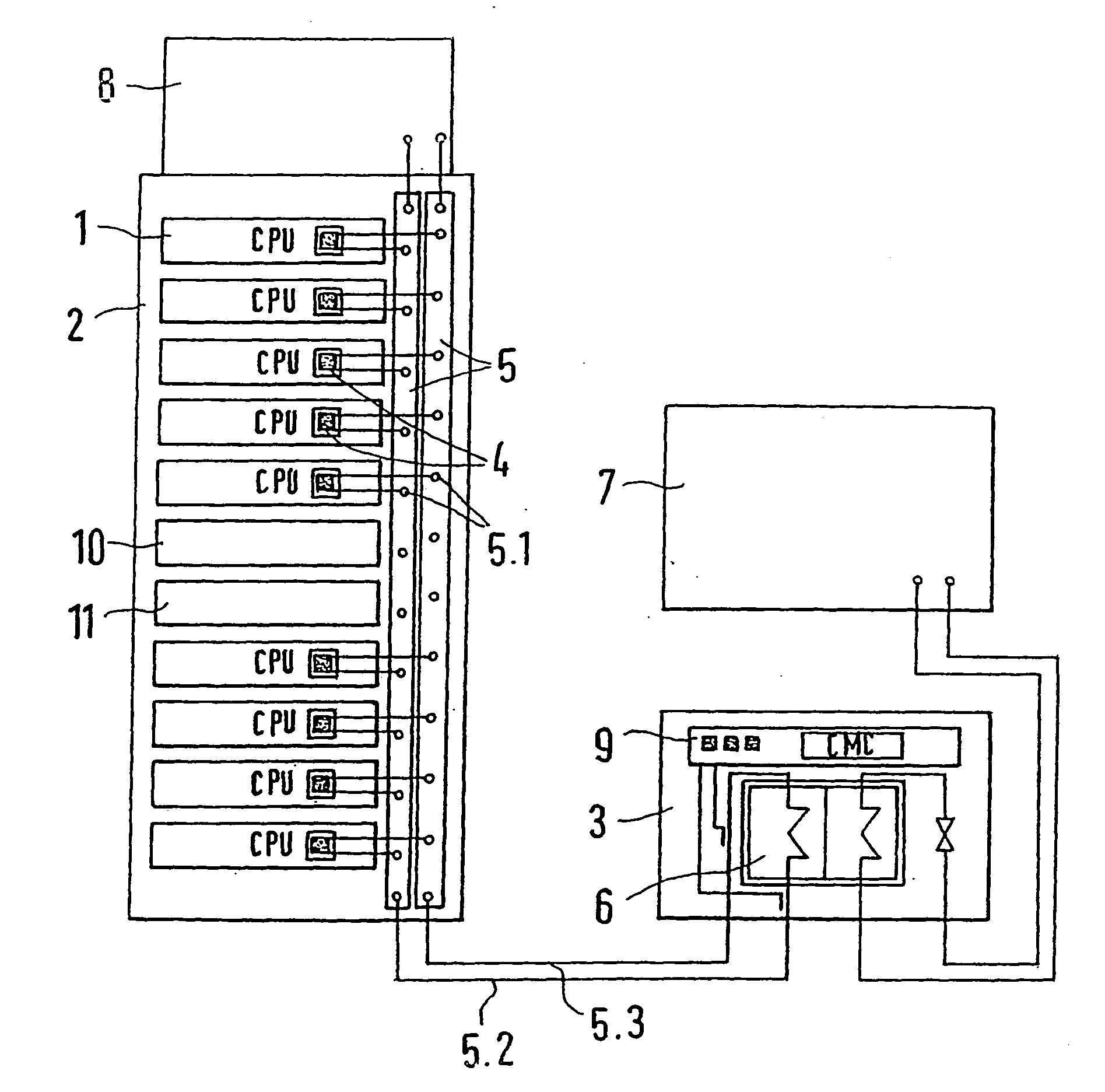
[0016] The electronic component groups 1 each has at least one central processing unit (CPU) 1.1 of high computing output as the main heat producer in a housing containing the electronic components group 1.

[0017] For cooling the electronic component group 1, particularly the processor units or computer units 1.1 embodied as integrated components, cooling elements 4 of the liquid cooling units, which have conduits, are applied in tight heat conducting contact to the component element body, through which the coolant is conducted over an as long as possible path. The liquid cooling units with the cooling elements 4 are connected via respective inlet branch lines and return branch lines by respective branch points 5.1 with coupling elements to a vertical section of a central liquid line system 5 extending in the rack. The central liquid line system 5 also has an inlet branch 5.2 and a return branch 5.3 for the coolant, wherein the vertical section arranged in the rack 2, or switchgear ...


PUM


Abstract

A liquid cooling system having cooling units individually assigned to electronic component groups housed in a rack or a switchgear cabinet, which are to be cooled, and having a monitoring and control arrangement for monitoring a cooling temperature. Effective cooling and temperature monitoring is obtained because the cooling units are liquid cooling units and are connected via branch points to a common central liquid line system integrated into the rack or the switchgear cabinet. The control and monitoring arrangement is for monitoring the cooling temperature in the central liquid line system and for emitting an error signal when a predetermined or a predeterminable threshold temperature in a liquid return branch is exceeded, or when a predetermined or predeterminable threshold temperature difference between a temperature in an inlet branch and a temperature in the return branch is exceeded, or when the liquid flow falls below a predetermined or predeterminable threshold value.

Description

BACKGROUND OF THE INVENTION [0001] 1. Field of the Invention [0002] This invention relates to a liquid cooling system having several cooling units, which are individually assigned to electronic component groups housed in a rack or switchgear cabinet and which are to be cooled, and also having a monitoring and control arrangement for monitoring the cooling temperature. [0003] 2. Discussion of Related Art [0004] A liquid cooling system is disclosed in German Patent Reference DE 196 09 651 C2 in connection with a switchgear cabinet air-conditioning arrangement. In this case, the liquid cooling system is designed, for example, as a cooling device or cooling unit with an air / water heat exchanger and represents a component of the entire air-conditioning arrangement, which is monitored and controlled or regulated by a higher-order monitoring and control arrangement. It is possible with the cooling system, together with the monitoring and control arrangement, to provide varied control conce...

Claims


Application Information

Patent Timeline
IPC IPC(8): G01K13/00F25D23/12F25D17/02H05K7/20
CPCF25D17/02H05K7/2079H05K7/20781
Inventor NICOLAI, MICHAELDORRICH, MARTINSTRACKBEIN, HEINRICHHAIN, MARKUSKREILING, JORG
Owner RITTALWERK RUDOLF LOH GMBH & CO KG
Why Eureka
Try Eureka