Toothed Wheel For a Play-Free Gear Spur Set

a technology of play-free spurs and gear sets, which is applied in the direction of gearing elements, belts/chains/gearrings, portability lifting, etc., can solve the problems of less suitable sintered partial rings, annular springs cannot be pre-tensioned during the mounting process, and the pressure load of support webs is increased

Inactive Publication Date: 2008-06-19
MIBA SINTER AUSTRIA
View PDF14 Cites 16 Cited by
  • Summary
  • Abstract
  • Description
  • Claims
  • Application Information

AI Technical Summary

Benefits of technology

[0009]As was already explained, the two partial rings need to be twisted against the pre-tensioning force of the annular spring in order to overlap their teeth. The assembly stop formed by the support web delimiting the through opening in the circumferential direction offers a simple constructional possibility for fixing said cover layer because it is merely necessary to insert for this purpose a spacer between the two support webs from the side of the partial ring comprising the through opening. Said spacer prevents a mutual turning back of the two partial rings into the initial position limited by the stop, so that the toothed wheel can be brought into engagement with the mating gear like a non-split toothed wheel before the spacer is removed and the teeth of the two partial rings are placed under a respective pre-tension in a resilient manner against the mutually opposing tooth flanks of the mating gear.

Problems solved by technology

As a result of the radial shortening of the support webs and the resulting reduction of the supporting surface for the annular spring, this known construction leads to an increased pressure load of the support webs, making such constructions less suitable for sintered partial rings.
This known construction has the disadvantage however that the annular spring cannot be pre-tensioned during the mounting process.
Apart from the fact that even in the case of such a construction the pre-tensioning of the helical spring is not possible prior to a tooth engagement with a chain or toothed belt, there are conditions that are not comparable to the arrangement of helical springs distributed over the circumference.

Method used


Image

  • Toothed Wheel For a Play-Free Gear Spur Set
  • Toothed Wheel For a Play-Free Gear Spur Set
  • Toothed Wheel For a Play-Free Gear Spur Set

Examples


Embodiment Construction

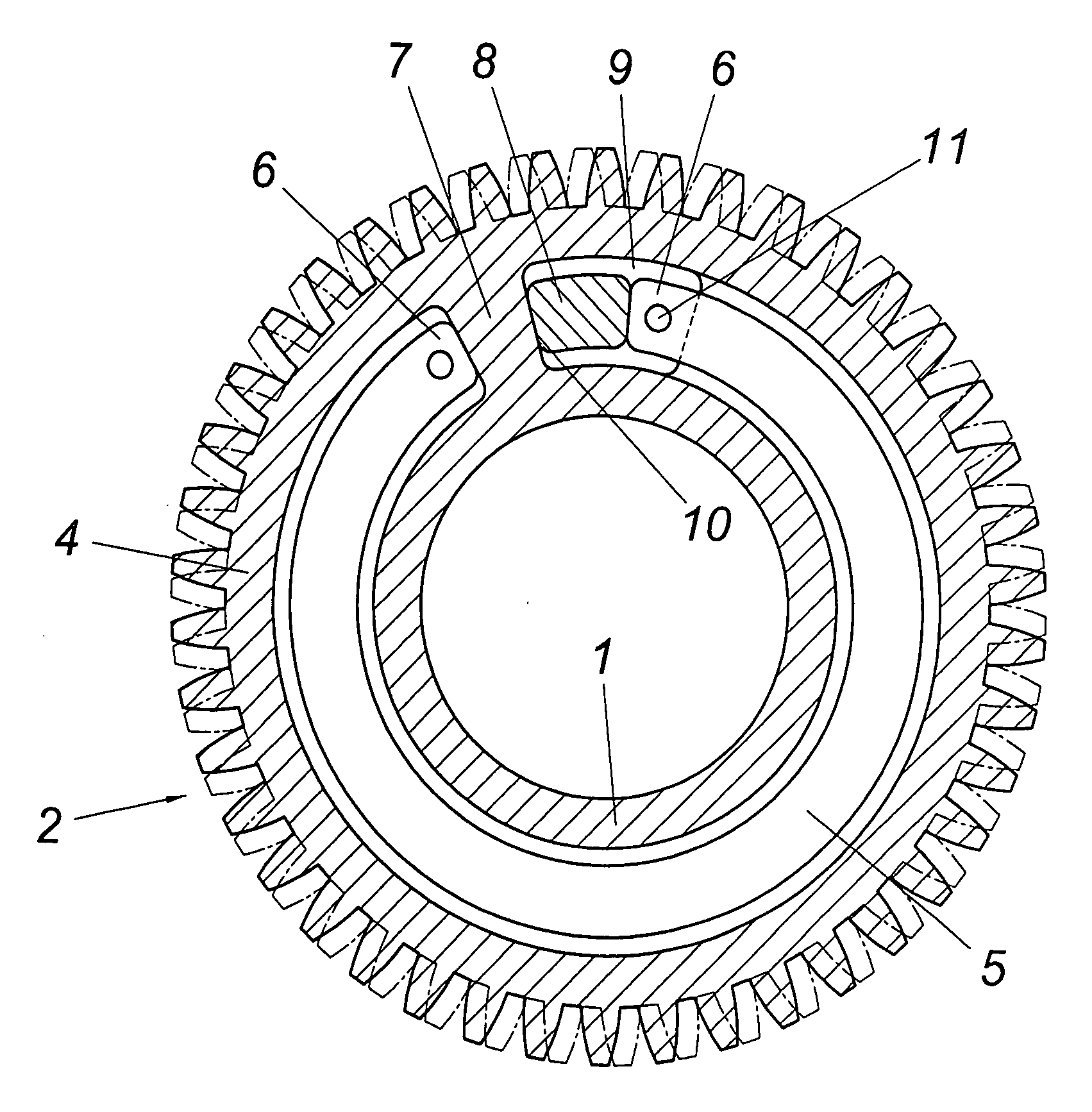
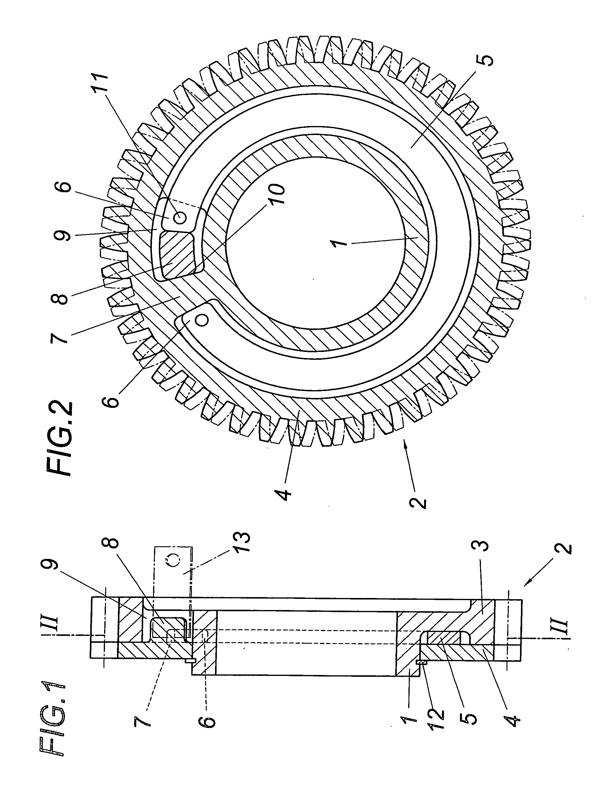
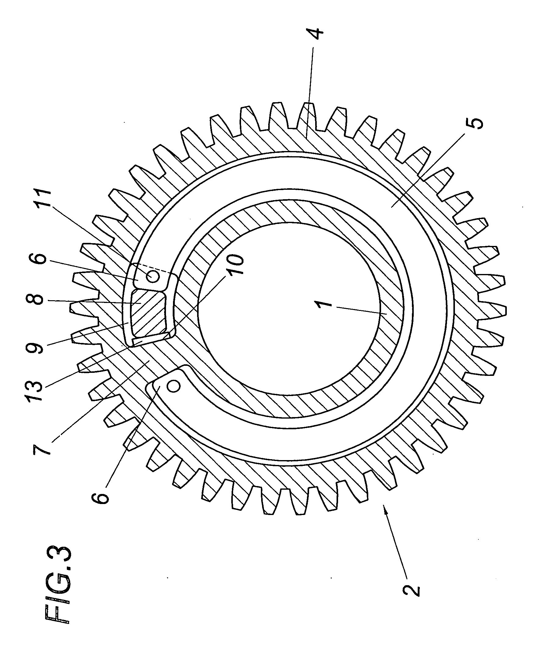
[0014]As can be seen in FIGS. 1 and 2, the illustrated toothed wheel consists of a hub 1 and a toothed ring 2 which is split along a plane perpendicular to the gear wheel axis into a ring piece 3 fixed to the hub and a ring crown 4 rotatably held on the hub 1. An annular ring 5 is provided between the ring piece 4 fixed to the hub and the ring crown 4 which is rotatable relative to the same, which annular spring encloses the hub and rests with its ends 6 opposite of each other in the circumferential direction on support webs 7 and 8 on the ring piece 3 on the one hand and the ring crown 4 on the other hand. Said support webs 7 and 8 lie behind one another in the circumferential direction of the toothed ring 2, with the support web 7 delimiting according to FIG. 2 a through opening 9 for the support web 8 of the ring crown 4 on the side averted from the associated end 6 of the annular spring 5. The arrangement is made in such a way that the support web 8 of the ring crown engages in ...


PUM


Abstract

A toothed wheel is described for a play-free spur gear set, comprising a hub (1), with a toothed ring (2) supported by the hub (1), which ring is split into two partial rings along a dividing plane normal to an axis, namely into a ring piece (3) fixed to the hub and a ring crown (4) mounted to rotate coaxially relative to the above, and an annular spring (5) enclosing the hub (1) with the circumferentially-opposed ends (6) resting on support webs (7, 8) embodied integrally with both partial rings, overlapping each other in the axial direction and arranged behind each other in the circumferential direction of the toothed ring. In order to avoid any overload of the partial rings produced by way of powder metallurgy and to ensure simple constructional conditions it is proposed that the support web (8) of one partial ring extends through the other partial ring in a through opening (9) with circumferential play and the support web (7) of the partial ring with the through opening (9) forms an assembly stop (10) defining the through opening (9) for the other support web (8).

Description

1. FIELD OF THE INVENTION[0001]The invention relates to a toothed wheel for a play-free spur gear set, comprising a hub, with a toothed ring supported by the hub, split into two partial rings along a dividing plane normal to an axis, namely into a ring piece fixed to the hub and a ring crown mounted to rotate coaxially relative to the above, and an annular spring enclosing the hub with the circumferentially-opposed ends resting on support webs embodied integrally with both partial rings, overlapping each other in the axial direction and arranged behind each other in the circumferential direction of the toothed ring.2. DESCRIPTION OF THE PRIOR ART[0002]In order to obtain a play-free gear spur set for transmitting alternating torques, the use of toothed wheels with a toothed ring split along a plane normal to an axis is known, with the two partial rings, namely a ring piece fixed to the hub and a ring crown mounted to rotate coaxially to the above, being clamped in a resilient manner ...

Claims


Application Information

Patent Timeline
Patent Type & Authority Applications(United States)
IPC IPC(8): F16H55/17F16H55/18
CPCY10T74/1987F16H55/18
Inventor SANDNER, CHRISTIAN
Owner MIBA SINTER AUSTRIA
Why Eureka
Try Eureka