Vehicle seat

Active Publication Date: 2013-09-19
ADIENT US LLC
View PDF18 Cites 5 Cited by
  • Summary
  • Abstract
  • Description
  • Claims
  • Application Information

AI Technical Summary

Benefits of technology

[0011]According to the above configuration, of the front lock unit and the rear lock unit separated from each other in the front-rear direction, the rear lock unit has the first lower end portion of the belt anchor bracket supported thereon rotatably in the front-rear direction

Problems solved by technology

If the strength of each of the lock means and the leg is to be enhanced to make them able to withstand such sea

Method used


Image

  • Vehicle seat
  • Vehicle seat
  • Vehicle seat

Examples


Embodiment Construction

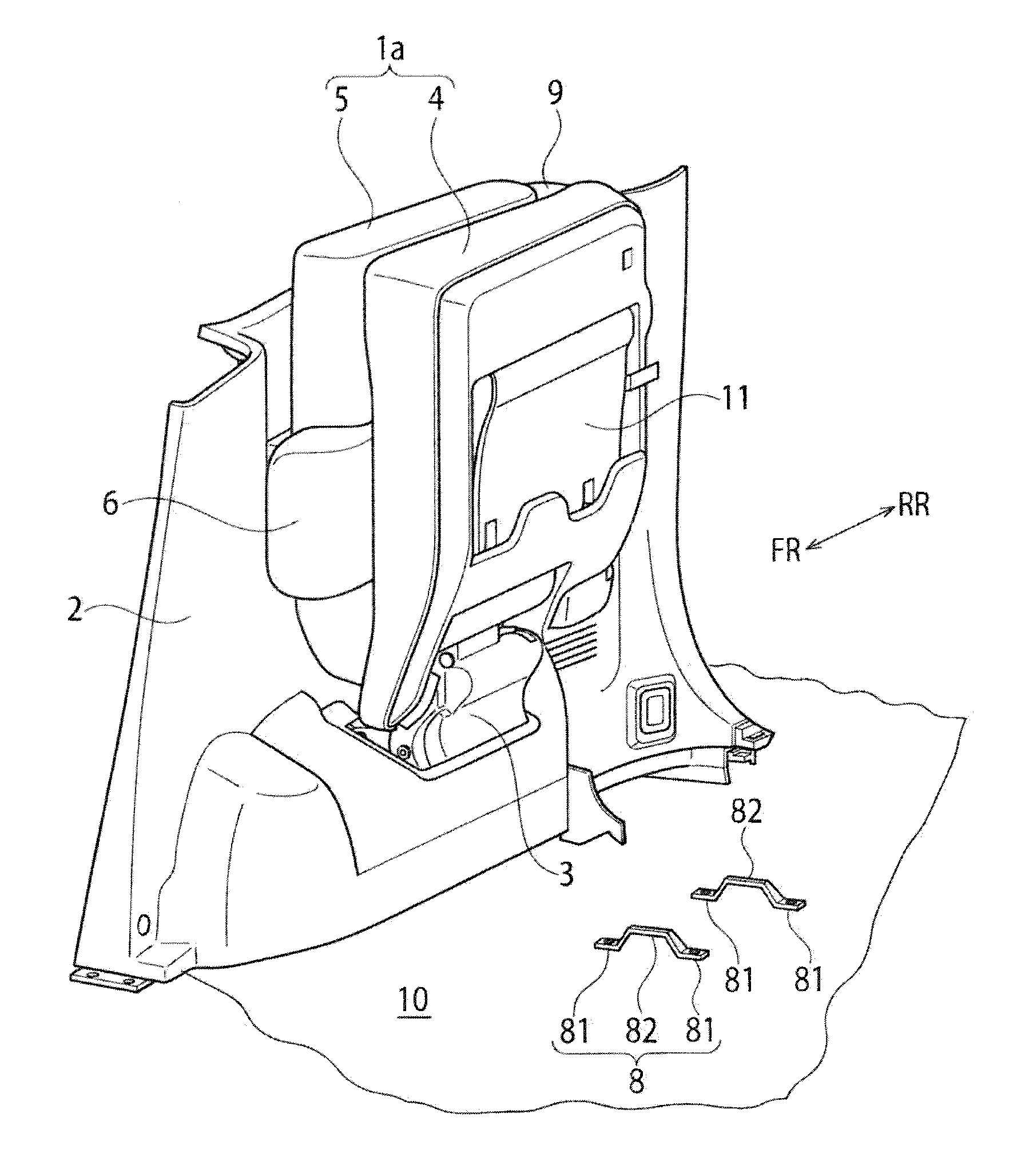
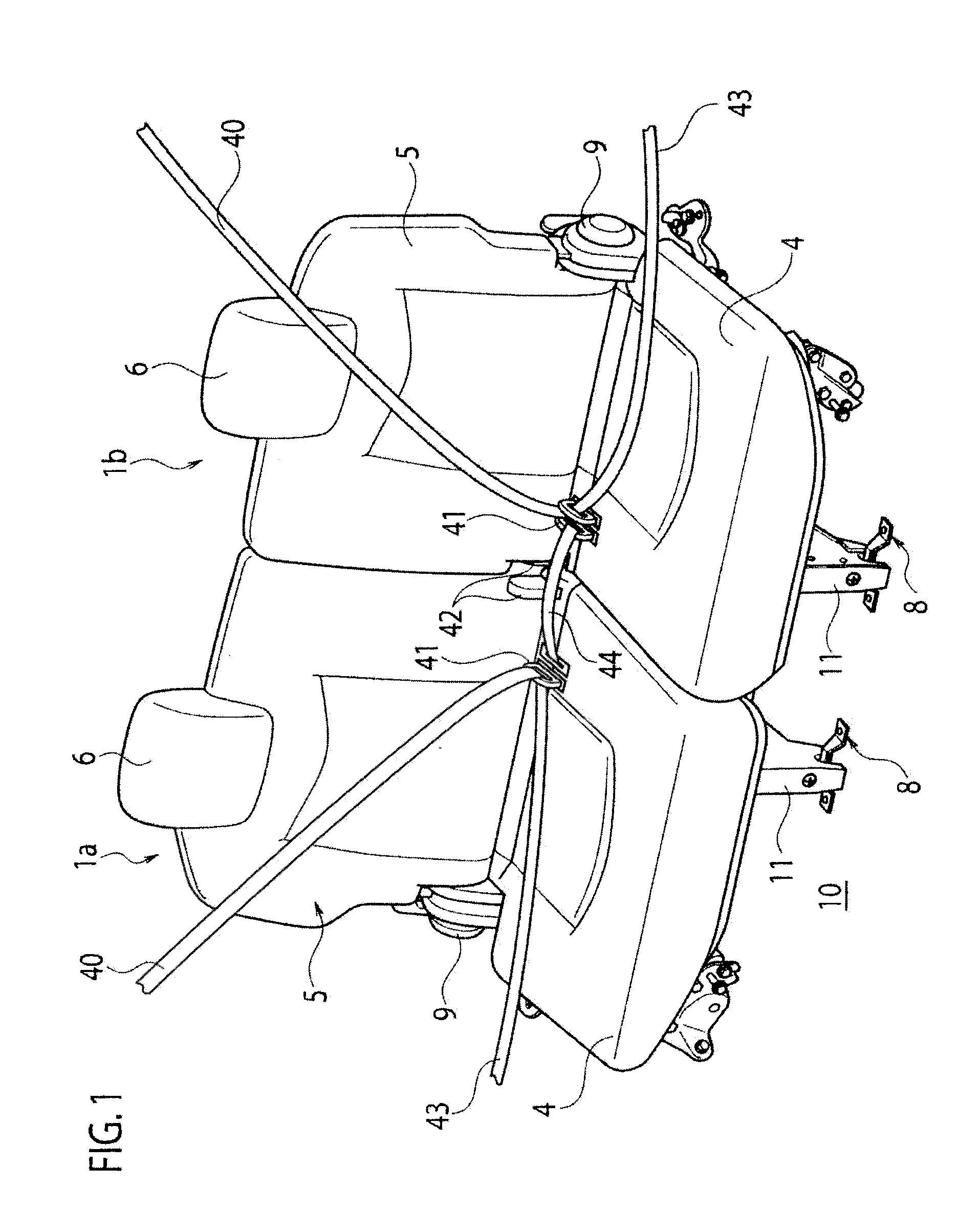
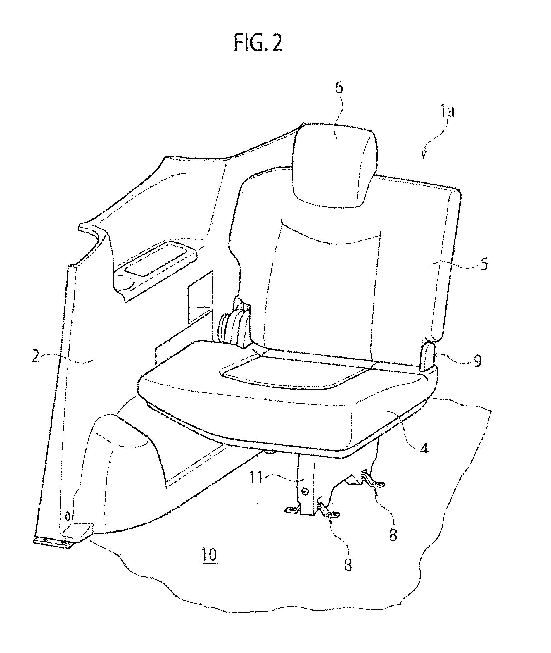
[0019]The object of providing a vehicle seat with a seatbelt anchor having improved strength without increasing the manufacturing costs of lock units and a leg is achieved by including: a seat cushion having one side supported on a side panel of a vehicle rotatably in a left-right direction of the vehicle; a leg hanging downward from the other side of the seat cushion and being capable of horizontally holding the seat cushion on a floor panel of the vehicle; a lock unit engageable with and disengageable from an engagement member provided to the floor panel; and a belt anchor bracket having a first lower end portion supported on the lock unit rotatably in a front-rear direction of the vehicle, a second lower end portion fixed to the leg, and an upper end portion supporting a seatbelt anchor rotatably in the front-rear direction.

[0020]Hereinbelow, an embodiment of the present invention will be described in detail with reference to FIGS. 1 to 7.

[0021]FIG. 1 shows seats 1a, 1b mounted o...


PUM


Abstract

One lower end portion of a belt anchor bracket is supported on a lock unit rotatably in a front-rear direction, the other lower end portion of the belt anchor bracket is fixed to a leg, and a seatbelt anchor is supported on an upper end portion of the belt anchor bracket rotatably in the front-rear direction.

Description

TECHNICAL FIELD[0001]The present invention relates to a seat for a vehicle such as an automobile.BACKGROUND ART[0002]As a related vehicle seat, there is a seat designed such that a lateral part of the seat on a vehicle body side is supported by a hinge mechanism so as to be rotatable between a position at which the seat is raised and a position at which one can sit thereon, and a lock device is provided to a leg of the seat given on the opposite side thereof from the vehicle body, i.e. the cabin side (see Patent Literature 1) . The lock device is formed of front lock means and rear lock means which are capable of engaging with front and rear engagement members fixed to a floor panel. While the rear lock means is in an engaged state, the front lock means is in a disengaged state, but the front lock means can be moved into engagement with the front engagement member by given lifting load applied to the seat cushion in a rear collision.CITATION LISTPatent Literature[0003][PTL 1] Japane...

Claims


Application Information

Patent Timeline
IPC IPC(8): B60N2/30B60N2/90
CPCB60N2/01583B60N2/3011B60R2022/021B60N2/688B60R22/26B60N2/3043
Inventor MIYAZAWA, MASAAKIKONDO, IKUO
Owner ADIENT US LLC
Why Eureka
Try Eureka