
Method for fabricating ceramic articles and ceramic articles produced thereby

Inactive Publication Date: 2006-02-09
CORNING INC
View PDF10 Cites 10 Cited by
  • Summary
  • Abstract
  • Description
  • Claims
  • Application Information

AI Technical Summary

Benefits of technology

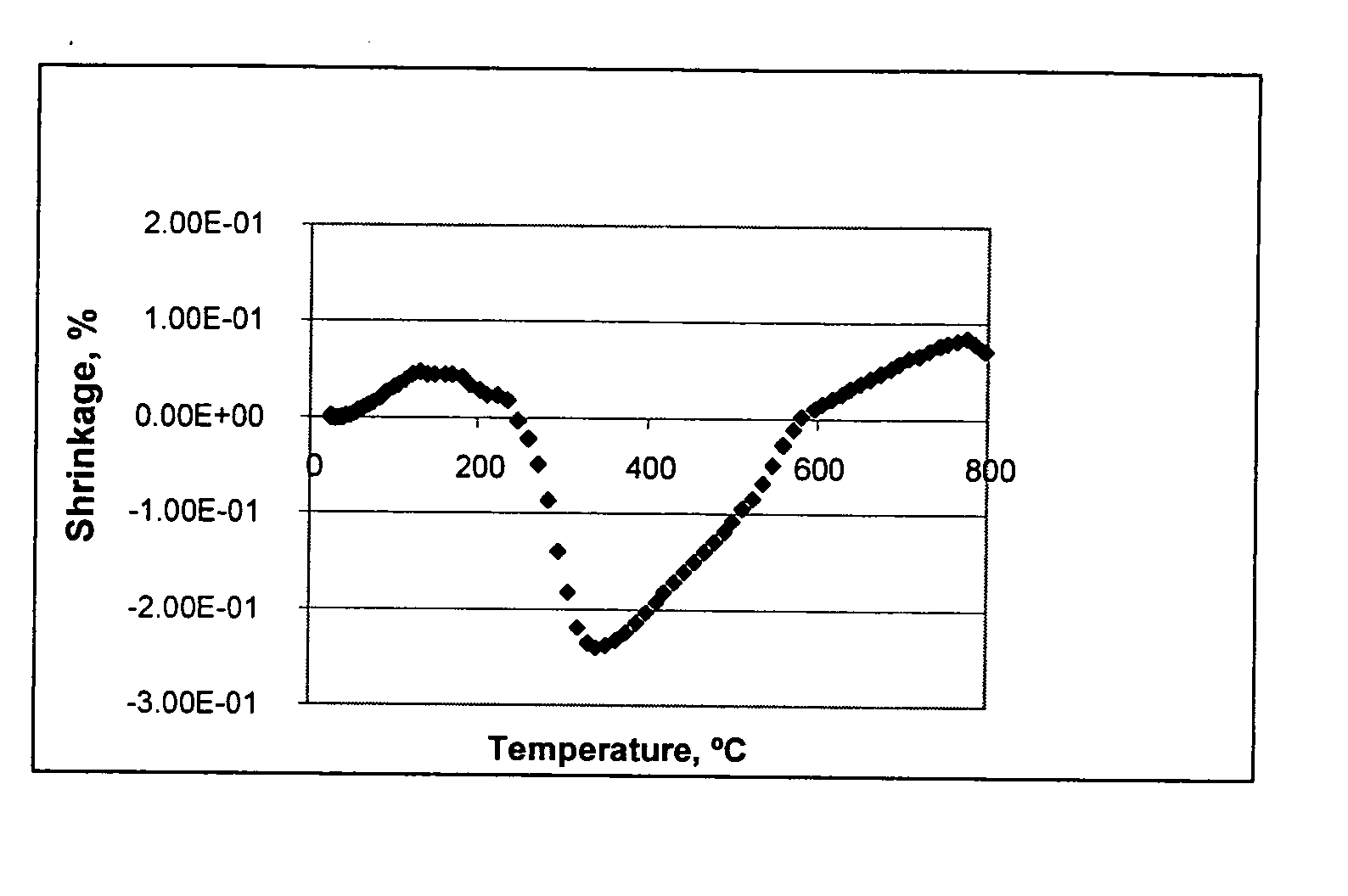
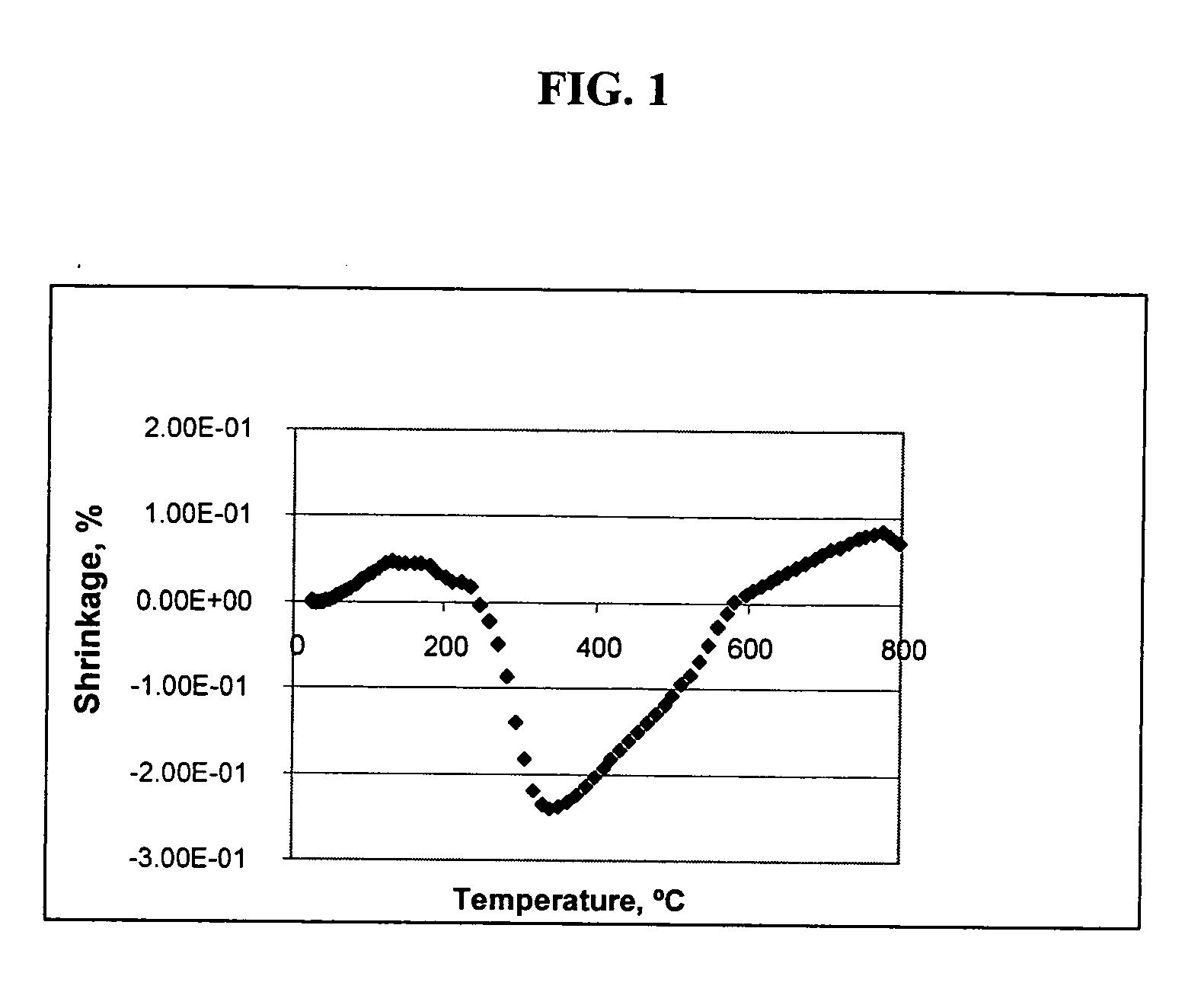
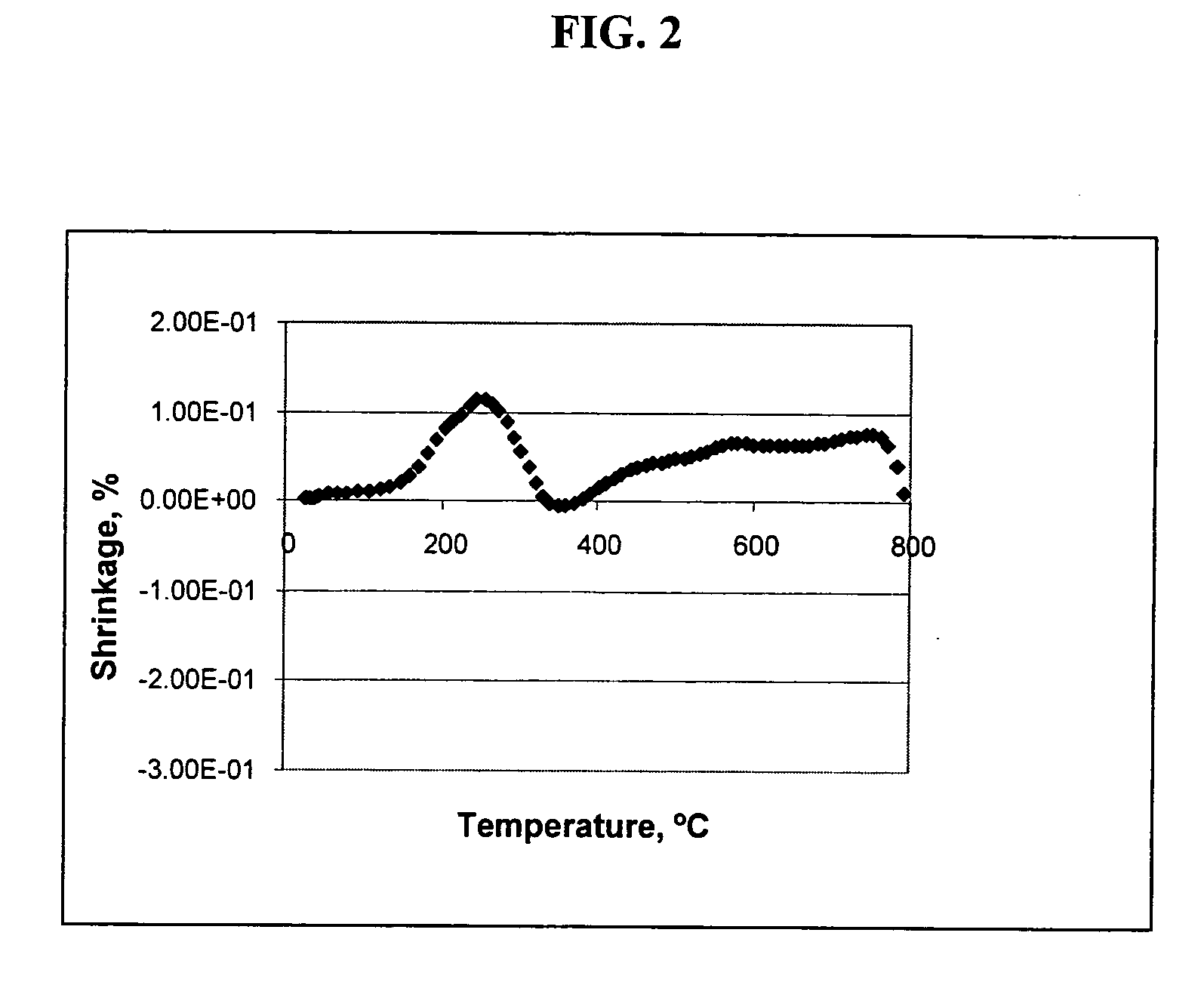
[0014] It has been found that by using organic and inorganic components for the binder, ceramic articles of the type described can be fired faster with less or no cracks. In particular the green bodies have improved strength in a temperature region between 300° C. to 900° C., and are therefore more resistant and less susceptible to cracking and being damaged during subsequent sintering. The preferred amount of the inorganic component, preferably a fibrous silicate mineral for providing improved strength in a temperature region between 300° C. to 900° C. is between 2-10%. One preferable fibrous silicate mineral is attapulgite clay. Furthermore, when using organic and inorganic components for the binder in small amounts (for example 1-3%), the fired strength of the structure may be improved.

Problems solved by technology

The formulations of binders meeting these requirements is complex and a large number of different binder formulations are known in the art.
Cellulose ether binders which burnout in the temperature region between 100° C.-600° C., and more specifically around 300° C., are difficult to remove without incurring distortion or breakage of the ceramic part.
Therefore, the major obstacle in working with plasticized mixtures including organic binders is that the subsequently-formed green ceramic article may crack when fired, particularly in thin walled-honeycomb structures.
The cracking is a result of internal stresses developed during the removal of large amounts of organics which causes excessive temperature or pressure gradients internal to the bodies.
These methods however, require expensive and sophisticated equipment and increase the cost of firing and manufacturing.

Method used


Image

  • Method for fabricating ceramic articles and ceramic articles produced thereby
  • Method for fabricating ceramic articles and ceramic articles produced thereby
  • Method for fabricating ceramic articles and ceramic articles produced thereby

Examples


examples

[0042] Samples are prepared according to the compositions provided in Table I below. The dry ingredients are weighed, and mixed with water and other batch components, followed by kneading in a stainless steel muller to form a plasticized batch which is then extruded into cellular honeycomb bodies consisting of multiple parallel channels of square cross section. The cellular bodies contain approximately 200 cells per square inch (csi) and have a wall thickness of 0.019 inches.

TABLE I1234567CompInvInvInvInvInvInvRaw MaterialsWt %Wt %Wt %Wt %Wt %Wt %Wt %Talc (MPS = mm)39.9639.1637.9936.0239.1637.9936.02α-Al2O321.5421.1420.7920.3221.1420.7920.32(MPS = mm)Al(OH)316.3516.3516.0215.3516.3516.0215.35(MPS = mm)Silica (Quartz)22.1521.3520.2018.3121.3520.2018.31(MPS = mm)Acti-gel 208 ®0.002.005.0010.002.005.0010.00(Attapulgite Clay)Methocel ™ F240M5.005.005.005.002.502.502.50(Methylcellulose)Graphite10.0010.0010.0010.0010.0010.0010.00(MPS = mm)Sodium Stearate1.001.001.001.001.001.001.00Water...


PUM

PropertyMeasurementUnit
Temperatureaaaaaaaaaa
Fractionaaaaaaaaaa
Fractionaaaaaaaaaa

Abstract

A method for fabricating a ceramic article which includes providing a batch comprising components of (i) a mixture of inorganic raw materials comprising talc, alumina, and silica; (ii) a binder comprising a water-soluble organic binder and a fibrous silicate mineral having a high aspect ratio in combination with a large surface area; and (iii) a polar solvent; mixing the batch components to form a homogenous and plasticized mass; shaping the plasticized mass into a green body wherein the green body has improved strength; and, sintering the green body by heating to a temperature and for a time to initiate and sufficiently achieve conversion of the green body into a fired ceramic article.

Description

RELATED APPLICATIONS [0001] This is a continuation-in-part application of U.S. patent application Ser. No. 10 / 911,083 filed Aug. 3, 2004 entitled “Method For Fabricating Ceramic Articles.”FIELD OF THE INVENTION [0002] The present invention relates generally to a method for fabricating ceramic articles from moldable powdered mixtures that are formed by mixing inorganic particulate raw materials with a binder system that includes a water-soluble organic binder and an inorganic binder, and water as a solvent. More particularly, the method relates to the manufacturing of cordierite articles having improved strength to resist cracking and damage during sintering. BACKGROUND OF THE INVENTION [0003] Popular cellular ceramic monoliths which are generally formed by extrusion, such as cordierite honeycomb substrates which find applications in catalytic converters, diesel particulate filters, electrically heated catalyst, and chemical processing catalyst, require binders and other similar aids...

Claims


Application Information

Patent Timeline
IPC IPC(8): C04B35/195C04B33/36
CPCC04B2235/6021C04B2235/5296C04B2235/96C04B2235/9607C04B35/185C04B35/195C04B35/6263C04B35/632C04B35/6365C04B2235/3206C04B2235/3217C04B2235/3218C04B2235/3418C04B2235/3445C04B2235/3463C04B2235/3481C04B2235/349C04B2235/449C04B2235/5228C04B2235/80
Inventor BEALL, DOUGLAS MUNROEPETERSON, IRENE MONATHOMPSON, DAVID JOHN
Owner CORNING INC
Learn More