Release and Retention of Viscosity Modifiers Based on Oil Temperature

a technology of viscosity modifier and oil temperature, which is applied in the direction of lubricant mounting/connection, separation process, filtration separation, etc., can solve the problems of engine oil creating hydrodynamic drag-related frictional losses, progressive loss of viscosity index and thickening power, and loss of oil viscosity index with temperature changes, etc., to achieve greater control of oil viscosity, reduce engine wear, and improve fuel economy

Inactive Publication Date: 2013-09-26
GM GLOBAL TECH OPERATIONS LLC
View PDF9 Cites 8 Cited by
  • Summary
  • Abstract
  • Description
  • Claims
  • Application Information

AI Technical Summary

Benefits of technology

[0017]The disclosed system is beneficial for permitting greater control of oil viscosity according to operating temperature, which can improve fuel economy and reduce engine wear. Sequestering all or a part of the molecules of the viscosity modifier from the lubricant until the lubricant reaches a temperature at which the viscosity modifier is useful allows the lubricant to have a lower viscosity at cold temperatures. Lower lubricant viscosity at cold temperatures requires lower cold cranking capacity of the battery. The disclosed lubrication system also reduces the amount of time a viscosity modifier is exposed to mechanical shear and heat, reducing degradation and oxidation of the viscosity modifier and reducing piston deposits and sludge formation associated with the degradation and oxidation. Finally, sequestering the viscosity modifier or modifiers from the lubricant at low temperatures removes the need to use the more expensive expandable viscosity modifiers.

Problems solved by technology

Engine oil creates hydrodynamic drag-related frictional losses when the engine is running.
Such formulations provide satisfactory, though not optimum, viscosity over much of the temperature range, but the oil viscosity still changes with changes in temperature.
Further, extended use of viscosity modifiers may result in a progressive loss of viscosity index and thickening power and in the formation of unwanted deposits and sludge over time.

Method used


Image

  • Release and Retention of Viscosity Modifiers Based on Oil Temperature
  • Release and Retention of Viscosity Modifiers Based on Oil Temperature
  • Release and Retention of Viscosity Modifiers Based on Oil Temperature

Examples


Embodiment Construction

[0028]A detailed description of exemplary, nonlimiting embodiments follows.

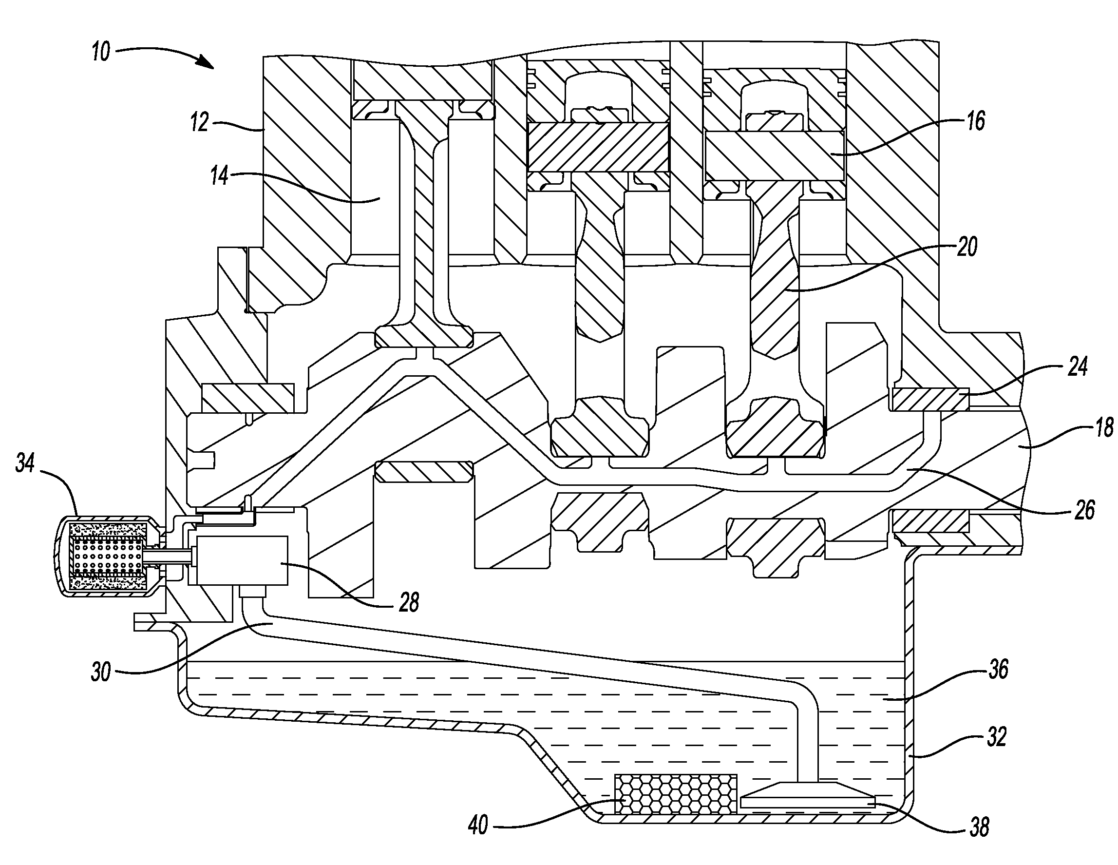
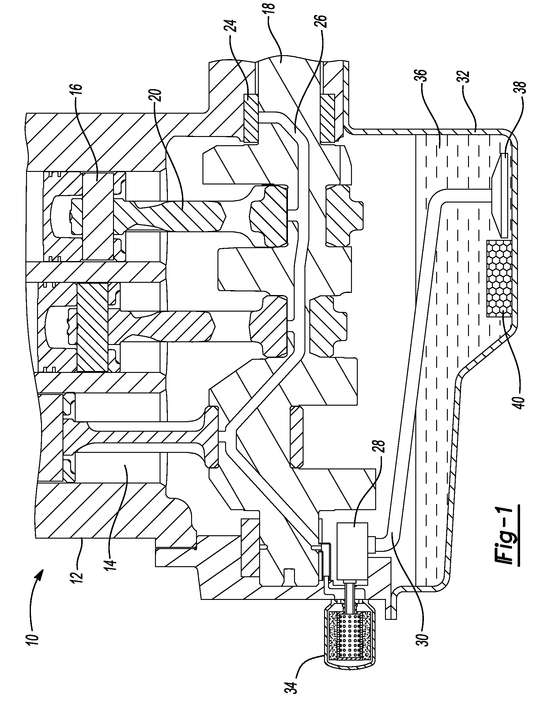
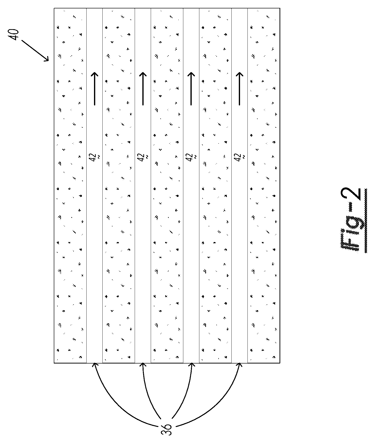
[0029]The lubrication system includes a lubricant having a viscosity modifier and a molecular sieve material having a pore size at temperatures below a threshold temperature selected to adsorb molecules of the lubricant viscosity modifier, wherein the molecular sieve material has a thermal expansion behavior causing a change in pore size as the threshold temperature is reached so as to release the viscosity modifier molecules at about the threshold temperature so that the viscosity modifier molecules are in the lubricant at temperatures from about the threshold temperature and higher.

[0030]The lubricant may be any of those used as engine oils, transmission fluids, hydraulic fluids, gear oils, marine cylinder oils, compressor oils, refrigeration lubricants, aviation turbine oils, gas turbine oils, passenger vehicle engine oils, commercial vehicle engine oils, industrial, marine, hydraulic, aviation, and drivel...


PUM

PropertyMeasurementUnit
threshold temperatureaaaaaaaaaa
sizeaaaaaaaaaa

Abstract

Disclosed are articles, lubrication systems, and methods that sequester lubricant viscosity modifiers via adsorption of the viscosity modifier molecules onto a molecular sieve material at lubricant temperatures below a threshold temperature and release of the viscosity modifier molecules from the molecular sieve material at lubricant temperatures at about the threshold temperature so that the viscosity modifier molecules are in the lubricant at temperatures from about the threshold temperature and higher. In this way, the viscosity modifier molecules are removed from the lubricant at temperatures where the lubricant has sufficient viscosity but released into the lubricant when they can useful increase the lubricant viscosity because it otherwise would be too low.

Description

FIELD OF THE SPECIFICATION[0001]The present invention relates to lubrication systems that experience large temperature variations, such as engine lubrication systems, and more specifically to controlling lubricant properties over a wide temperature span.INTRODUCTION TO THE DISCLOSURE[0002]This section provides information helpful in understanding the invention but that is not necessarily prior art.[0003]Engine oil lubricates moving components of an engine. For example, oil may lubricate pistons that reciprocate in cylinders, a crankshaft that rotates on bearings, and a camshaft that drives intake and exhaust valves. Oil reduces friction-related wear in the engine. Oil may also coat metal components to inhibit corrosion. A vehicle engine typically includes an oil pan that is mounted to the engine block. Lubricating oil drains from the engine block into and collects in the oil pan sump before being pumped from the oil pan and recirculated through the engine again.[0004]Automotive vehi...

Claims


Application Information

Patent Timeline
Patent Type & Authority Applications(United States)
IPC IPC(8): F16N39/06F01M9/00B01D35/02F16H57/04F01D25/18F01M11/03F01M1/02F16N7/38
CPCF01D25/18F01M9/02F01M2001/1014F01M2011/0029F16N39/00F16N2039/007
Inventor MORDUKHOVICH, GREGORYSCHNEIDER, ERIC W.
Owner GM GLOBAL TECH OPERATIONS LLC
Why Eureka
Try Eureka