Method and apparatus for laser cutting

a laser cutting and laser cutting technology, applied in the direction of polarising elements, instruments, manufacturing tools, etc., can solve the problems of affecting cutting speed, multi-focal cutting methods, and providing optimum power ratios

Active Publication Date: 2013-10-24
HIGHCON SYST
View PDF28 Cites 16 Cited by
  • Summary
  • Abstract
  • Description
  • Claims
  • Application Information

AI Technical Summary

Benefits of technology

[0017]The designed ratio between the reflected and transferred components of the original beam at the beam splitter may determine the power ratio between the R-beam and D-beam at the two focal points. Further, the phase

Problems solved by technology

However existing multi-focal cutting methods suffer from at least one of the following deficiencies.
Some of them cannot provide an optimum power ratio between the first and the second focal points, this may affect the cutting speed.
Most of the existing systems have complex and expensive structure in order to handle the high power laser that is used.
Exemplary expensive structures may include different coatings of

Method used


Image

  • Method and apparatus for laser cutting
  • Method and apparatus for laser cutting
  • Method and apparatus for laser cutting

Examples


Embodiment Construction

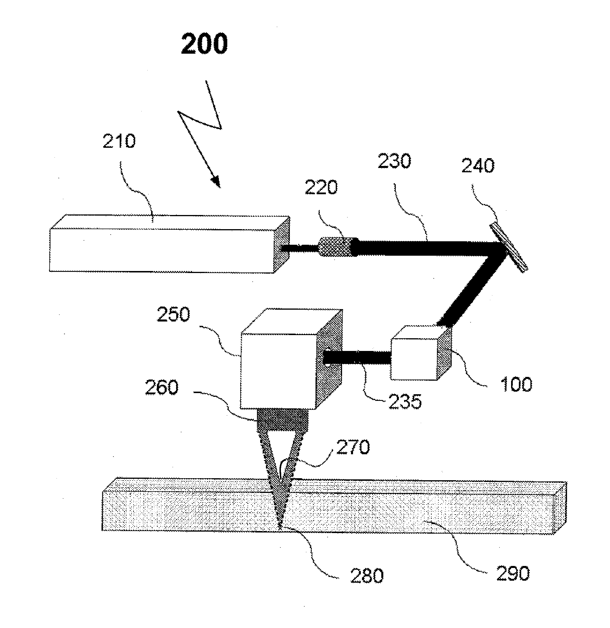
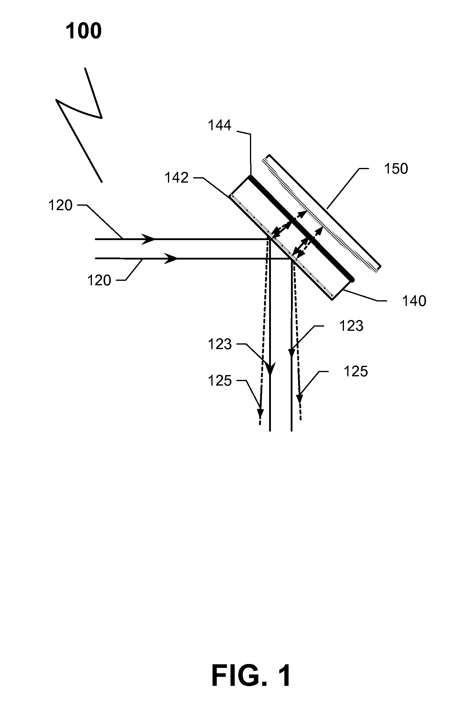
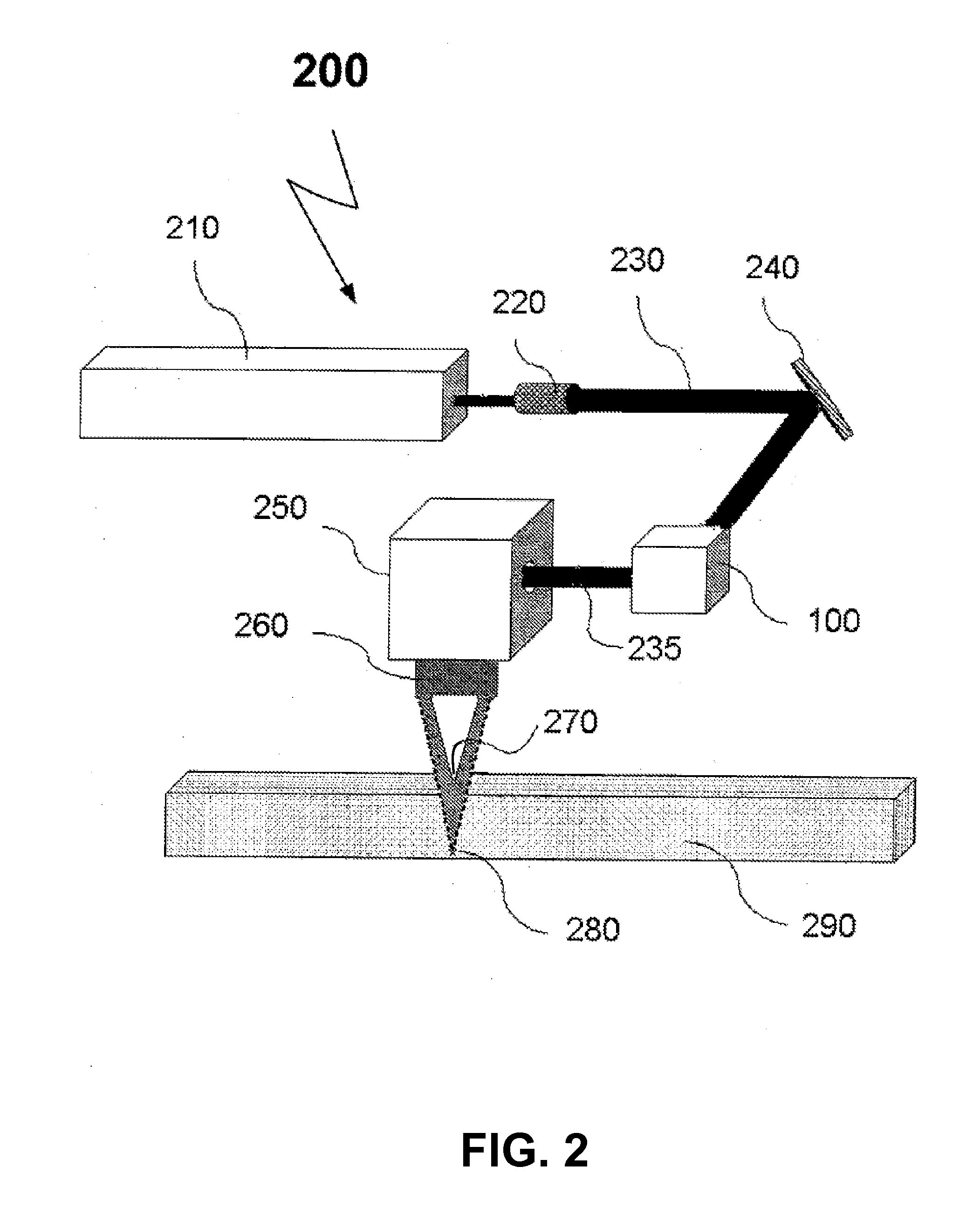
[0028]Turning now to the figures in which like numerals represent like elements throughout the several views, exemplary embodiments of the present disclosure are described. For convenience, only some elements of the same group may be labeled with numerals. The purpose of the drawings is to describe exemplary embodiments and is not for production purpose. Therefore features shown in the figures were chosen only for convenience and clarity of understanding thus the drawings are drawn out-of-scale.

[0029]In the following description, for purposes of explanation, numerous specific details are set forth in order to provide a thorough understanding. It will be apparent, however, to one skilled in the art that the invention may be practiced without these specific details. In other instances, structure and devices are shown in block diagram form in order to avoid obscuring the invention. Moreover, the language used in this disclosure has been principally selected for readability and instruct...


PUM

PropertyMeasurementUnit
Fractionaaaaaaaaaa
Fractionaaaaaaaaaa
Thicknessaaaaaaaaaa

Abstract

Method and system for laser cutting is disclosed. Using a novel dual-focus optical conversion unit. The dual-focus optical conversion unit may comprise a beam splitter and a convex mirror. The beam splitter may be insensitive to the polarization of an incident beam. The convex mirror may be placed beyond and parallel to the beam splitter, wherein the surface of the convex mirror may be coated with a reflective phase-retarder coating.

Description

CROSS-REFERENCE TO RELATED APPLICATIONS[0001]This application is being filed under 37 U.S.C. 111 as a continuation application (by-pass application) of International Application Number PCT / IL2011 / 000774, which has an international filing date of Sep. 27, 2011 and which claims priority to the following U.S. provisional application for patent: Ser. No. 61 / 405,664 filed on Oct. 22, 2010. This application claims the benefit of the priority date Oct. 22, 2010 under 37 U.S.C. 120 as a continuation of PCT / IL2011 / 000774, which claims priority as previously stated. The International Application Number PCT / IL2011 / 000774 is co-pending at the filing of this application and includes at least one common inventor. This application incorporates the above-identified International Application and United States Provisional application by reference in their entirety.TECHNICAL FIELD[0002]The present disclosure relates to the field of laser cutting process and more particularly to laser cutting process w...

Claims


Application Information

Patent Timeline
IPC IPC(8): G02B27/14G02B26/10
CPCG02B27/14G02B26/10B23K26/067B23K26/0676B23K26/38
Inventor DVORKIN, LEV
Owner HIGHCON SYST
Why Eureka
Try Eureka