Display device

a display device and display technology, applied in the field of display devices, can solve the problems of difficult to decrease the width of the peripheral edge of the display unit, difficult to decrease the size and difficult to decrease the thickness of the display device, etc., to achieve simple operation, improve workability, and thin and light

Inactive Publication Date: 2014-02-06
ORION ELECTRIC CO LTD
View PDF3 Cites 3 Cited by
  • Summary
  • Abstract
  • Description
  • Claims
  • Application Information

AI Technical Summary

Benefits of technology

[0009]The invention is made in view of the above-described circumstances, and it is an object of the invention to provide a display device which may be decreased in thickness and weight by a minimum number of components. Further, it is an object of the invention to provide a display device which may be assembled with satisfactory workability at low cost. Furthermore, it is an object of the invention to provide a display device which realizes a narrow frame by decreasing a width of a peripheral edge of a display unit and improves designability. Moreover, it is an object of the invention to provide a stable display device even when the size of a stand decreases by lowering a gravity center position of the display device.
[0010]Further, it is an object of the invention to provide a display device which may be decreased in size and thickness at low cost in consideration of improvement in quality of a sound. Furthermore, it is an object of the invention to provide a display device capable of suppressing a chatter noise phenomenon generated by the interference between components through the vibration of a speaker.
[0025]According to the configuration of the invention, since the resinous front bezel constituting the display panel assembly serves as the front cabinet of the related art and the metallic back chassis serves as the back cabinet of the related art, it is possible to manufacture the display device by assembling a minimum number of components on the basis of the display panel assembly and hence to provide the display device which is thin and light. Further, it is possible to assemble the display device by a simple operation of just sequentially assembling the components such as the speaker constituting the display device or various substrates on the basis of the display panel assembly and to provide a display device which has improved workability and low cost. Furthermore, since the front bezel constitutes the exterior of the display device instead of the front cabinet of the related art and the width of the front bezel directly becomes the width of the peripheral edge of the display unit in the display device, it is possible to narrow the frame of the peripheral edge of the display unit and hence to provide a display device having excellent designability. Moreover, since the components of the display device may be integrally disposed at the comparatively lower side of the display panel assembly, it is possible to define the gravity center of the display device at a low position. Accordingly, it is possible to provide a stable display device which does not easily fall, for example, even when the installation area of the stand decreases.
[0026]Further, since the small hole is formed in the second cover member disposed at the rear surface of the display panel assembly, it is possible to improve the quality of the sound of the speaker while realizing a decrease in the size of the display device. Furthermore, since the inner spaces of the second cover member and the first cover member are shared by providing the connection hole, it is possible to further improve the quality of the sound of the speaker. Moreover, since the plurality of protrusion portions are provided in the second cover member so as to contact the back chassis, it is possible to suppress the vibration of the speaker and hence to suppress the generation of the chatter noise caused by the interference between the components without providing a separate vibration-proof member.

Problems solved by technology

Further, since the inner components are attached on the basis of the reinforcement plate or the chassis and the exterior of the device is formed by the front cabinet and the back cabinet, a decrease in thickness is difficult.
As a result, it is difficult to decrease the width of the peripheral edge of the display unit.
At the same time, it is difficult to decrease the size and the thickness of the display device.
Further, since there is a need to provide a separate cushion member for suppressing a chatter noise phenomenon caused by the interference between the components through the vibration of the speaker, there is a concern that the number of components increases.

Method used


Image

  • Display device
  • Display device
  • Display device

Examples


Embodiment Construction

[0042]Hereinafter, an embodiment as a best mode for carrying out the invention will be described by referring to FIGS. 1 to 15. Furthermore, the invention may be also applied to a configuration other than those of the embodiment without departing from the gist of the invention.

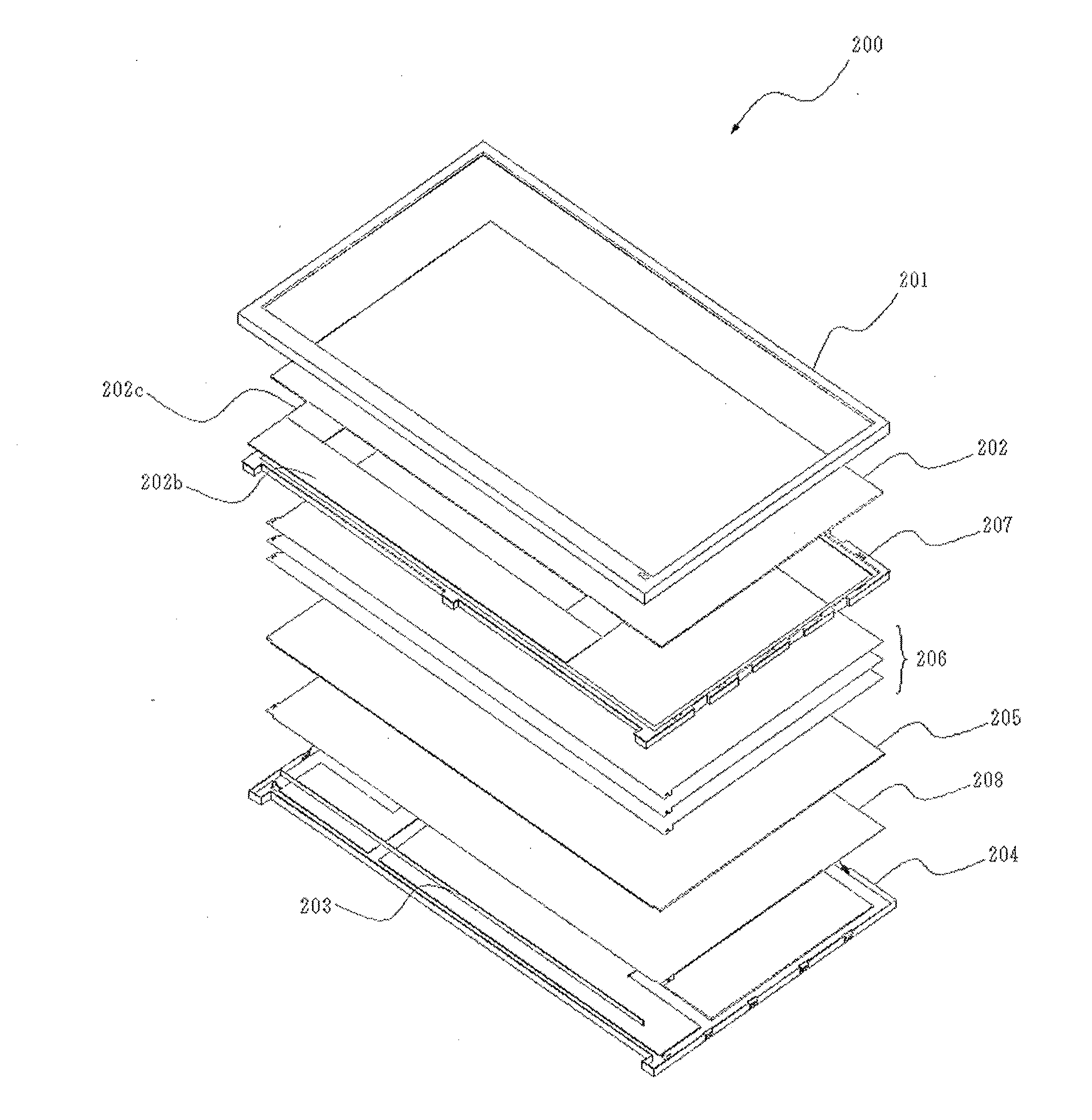
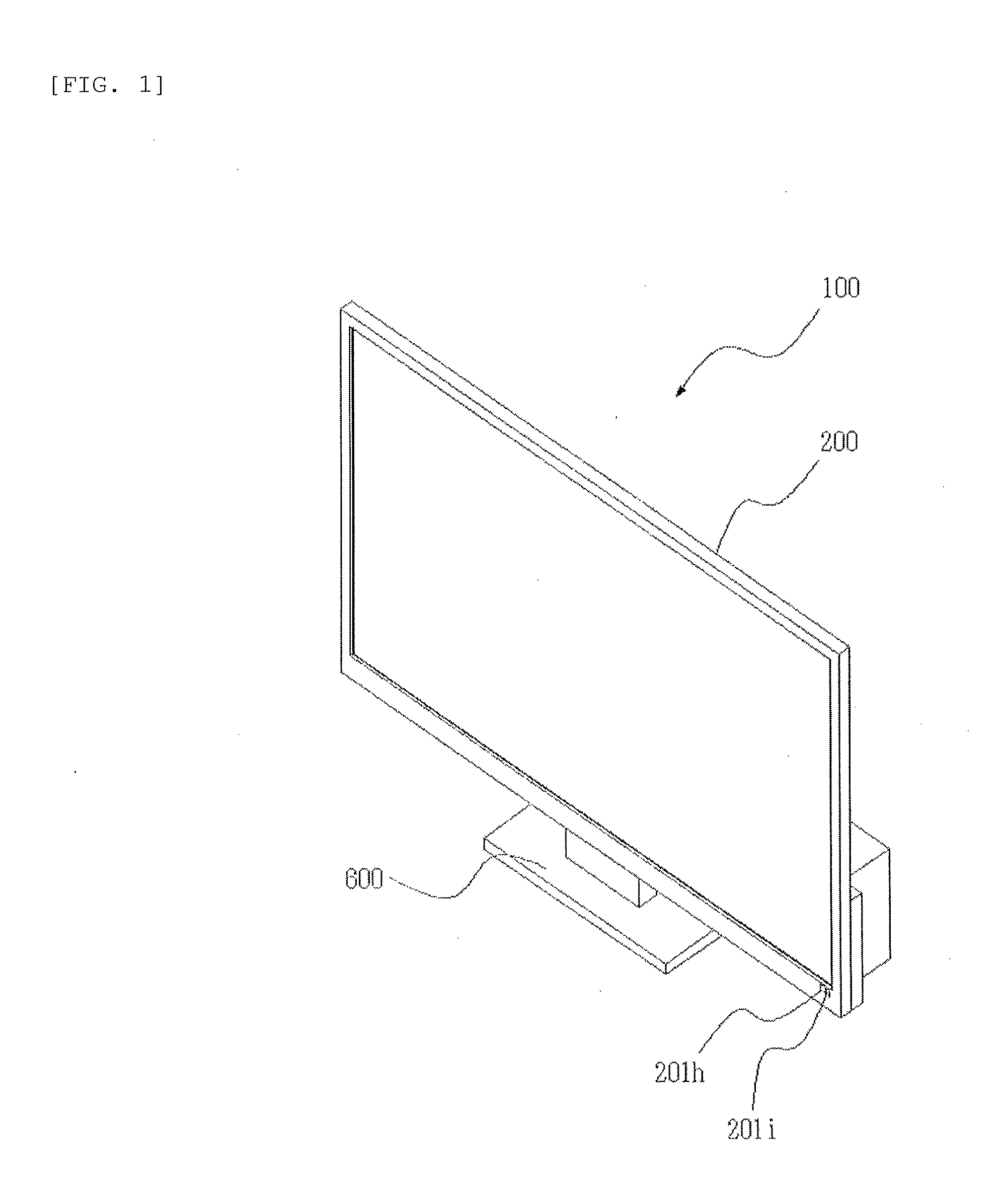
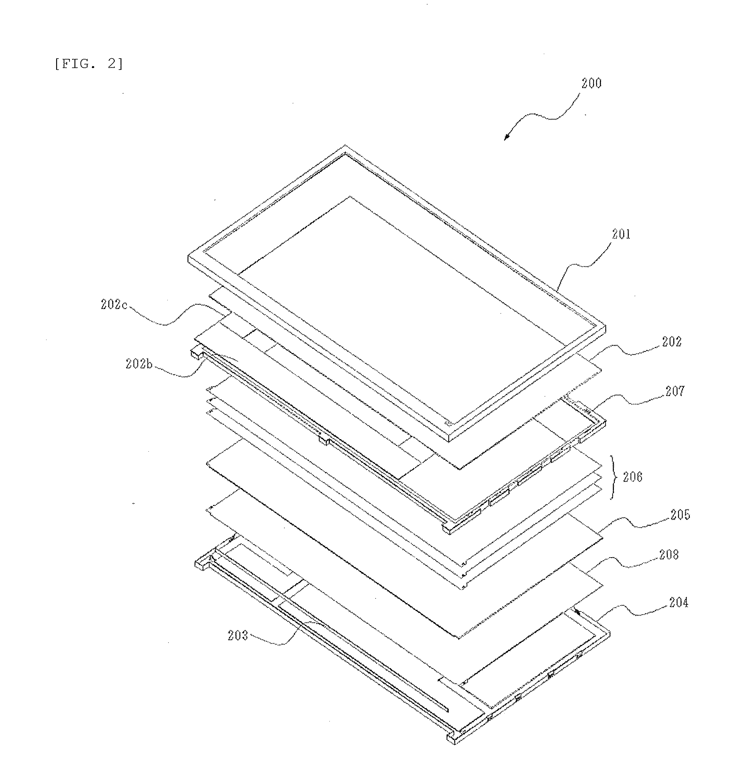
[0043]FIG. 1 is a front perspective view illustrating a display device of an embodiment of the invention, and FIG. 2 is an exploded perspective view illustrating a configuration of a display panel assembly of the embodiment of the invention. In the drawings, respectively provided are a display device 100, a display panel assembly 200 which constitutes a display unit of the display device 100, a front bezel 201, a liquid crystal cell 202 which displays a video picture thereon, a light source 203 which causes light to be transmitted through the liquid crystal cell 202 from the rear side thereof, a back chassis 204, a light guiding plate 205 which receives the light emitted from the light source 203 from one end ...


PUM

PropertyMeasurementUnit
flexibleaaaaaaaaaa
heightaaaaaaaaaa
widthaaaaaaaaaa

Abstract

A display device includes a display panel assembly in which a member having a liquid crystal cell and displaying a video picture thereon is built in a space formed by a front bezel and a back chassis. The front bezel serves as a front cabinet and the back chassis serves as a back cabinet. A control substrate is disposed in the rear surface of the back chassis, and a first cover member which covers the control substrate and a second cover member which is connected to the first cover member so as to substantially form an inverse T-shape and covers the other component are attached to the rear surface.

Description

BACKGROUND OF THE INVENTION[0001]1. Field of the Invention[0002]The present invention relates to a display device such as a monitor or a television receiver that displays a video picture thereon.[0003]2. Description of the Related Art[0004]As a recent display device, a thin display device with a liquid crystal cell having a small depth compared to the height and the width has been widely used. Such a thin display device is equipped with a circuit board which supplies power or a circuit board which controls a signal input from the outside and displays a video picture in the liquid crystal cell. Then, there have been various attempts to simplify a structure of the display device, realize a decrease in the weight and the thickness of the display device, or improve the designability of the display device.[0005]For example, Japanese Patent Application Laid-Open No. 2000-315054 discloses a structure in which the inside of a casing formed by a front cabinet having a display window and a ba...

Claims


Application Information

Patent Timeline
Patent Type & Authority Applications(United States)
IPC IPC(8): H05K7/04G02F1/1335
CPCG02F1/1336H05K7/04H04N5/64
Inventor TANAKA, YOSHIMOTOMUKOUGAWA, HIDENOBU
Owner ORION ELECTRIC CO LTD
Why Eureka
Try Eureka