Disk drive

a technology of disk drive and drive body, which is applied in the direction of magnetic recording, data recording, instruments, etc., can solve the problems of increased weight of the turntable so made, decreased strength of the turntable, and inability to work, so as to facilitate the disassembly of the disk drive

Inactive Publication Date: 2009-05-26
PANASONIC CORP
View PDF11 Cites 18 Cited by
  • Summary
  • Abstract
  • Description
  • Claims
  • Application Information

AI Technical Summary

Benefits of technology

[0038]The invention was made to solve the problems inherent in the conventional techniques, and an object thereof is to provided a disk drive which can facilitate the installation work of the turntable and ensure the prevention of dislodgement without reducing the flexibility of the dislodgement preventive portion even when the overall thickness of the disk drive is reduced and which can reduce the unnecessary space underneath the lower surface of the turntable to thereby enable the reduction in thickness and weight of the disk drive.
[0039]In addition, the invention was made to solve the problems inherent in the conventional techniques and an object thereof is to provide a disk drive which can reduce the thickness and weight of the base portion to thereby reduce the overall thickness and weight thereof while maintaining the strength of the base portion 101 and the stability of the magnetic circuit at the outer circumferential portion of the stator core and which can further enable the improvement in soldering work that is to be implemented on the circuit board, as well as the improvement in accuracy and workability which are required when the disk drive is mounted in the housing.

Problems solved by technology

(1) In the conventional general disk drives, since the turntable is made by drawing or cutting a sheet metal, there have been caused problems that the weight of the turntable so made is increased, and when the thickness of the turntable is attempted to be reduced with a view to reducing the weight and thickness thereof, the strength of the turntable is decreased, and that a complex and trouble some working is required for a center portion thereof where a spindle is to be fixed.
(2) In addition, since it is a general practice to form the turntable into a flat shape by drawing or cutting a sheet metal, there has been caused a problem that an unnecessary space is produced between a lower surface of the turntable and the bearing portion and the bearing holding portion, and hence the overall thickness of the disk drive becomes thick, making it difficult to make the disk drive thinner.
(3) Since the hook portions 116 is made up of a separate member from the turntable 109, there have been caused problems that the number of component is increased and that the number of manufacturing manhours required for a press bonding or welding process of fixing the hook portion 16 to the lower surface of the turntable 109 is increased, and additionally, since when attempting to thin the disk drive 100, a vertical length of the hook portion 116 is reduced, there has been caused a problem that a sufficient flexibility cannot be imparted to the hook portion 116, thereby making it difficult to mount the hook portion on the turntable 109.
(4) Since the disk holding claw 113 is not only pushed to a center side of the disk holding portion 112 but also slides downwards when the disk D is installed, there has been caused a problem that the predetermined gap 118 becomes necessary on the upper surface side of the turntable 119 for allowing the disk holding claw 113 to slide downwards, this increasing the overall thickness of the disk drive.
(5) In addition, since a punched sheet metal is used as the base portion 101, there have been caused problems that not only the thickness but also the weight of the disk drive is increased, thereby making it difficult to reduce the weight and thickness of the disk drive and that when attempting to reduce the thickness, the mechanical strength thereof is reduced.
Note that as with the spindle motor in (Patent Document No. 2), while in the event that the distal end portions of the tees of the stator core are brought into abutment with the base plate, a predetermined strength can be obtained, since the stator core and the base plate are made to abut with each other, there has been caused a problem that a magnetic circuit made up of the stator core and the magnet becomes unstable, the efficiency being thereby deteriorated.
(7) Since the disk drive 100 needs to be mounted on the housing via a spacer, there has been caused a problem that the number of components is increased, and since dimensional errors are accumulated, there has been caused a problem that the mounting tolerance is increased.
However, as this actually occurs, since the hook portions 116 are provided on the lower surface of the turntable 109, a direct pressing force cannot be applied to the hook portions 116, a problem being thereby caused that the disassembling for rectification becomes difficult once the disk drive has been assembled.
(12) Since the base portion 101 is strongly fixed to the bearing holding portion 102 by plastically deforming the annular portions provided on the lower side of the bearing holding portion 102 through pressing, it becomes difficult to secure a vertical accuracy of the bearing portion 103 based on the mounting surface provided on the base portion 101 via which the disk drive is mounted in the housing due to the effect of the warping of the base portion 101, and additionally, dispersion in height based on the mounting surface tends to be generated easily, a problem being thereby provided that the thinning of the disk drive is difficult to be realized.

Method used


Image

  • Disk drive
  • Disk drive
  • Disk drive

Examples


embodiment 1

[0135]Hereinafter, an embodiment of the invention will be described using respective drawings.

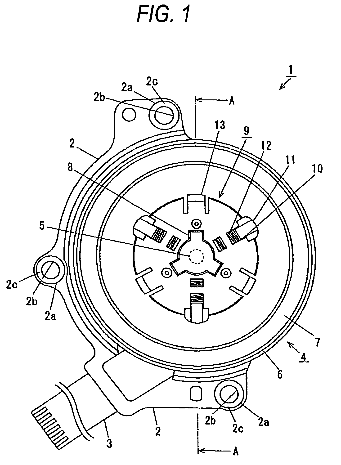
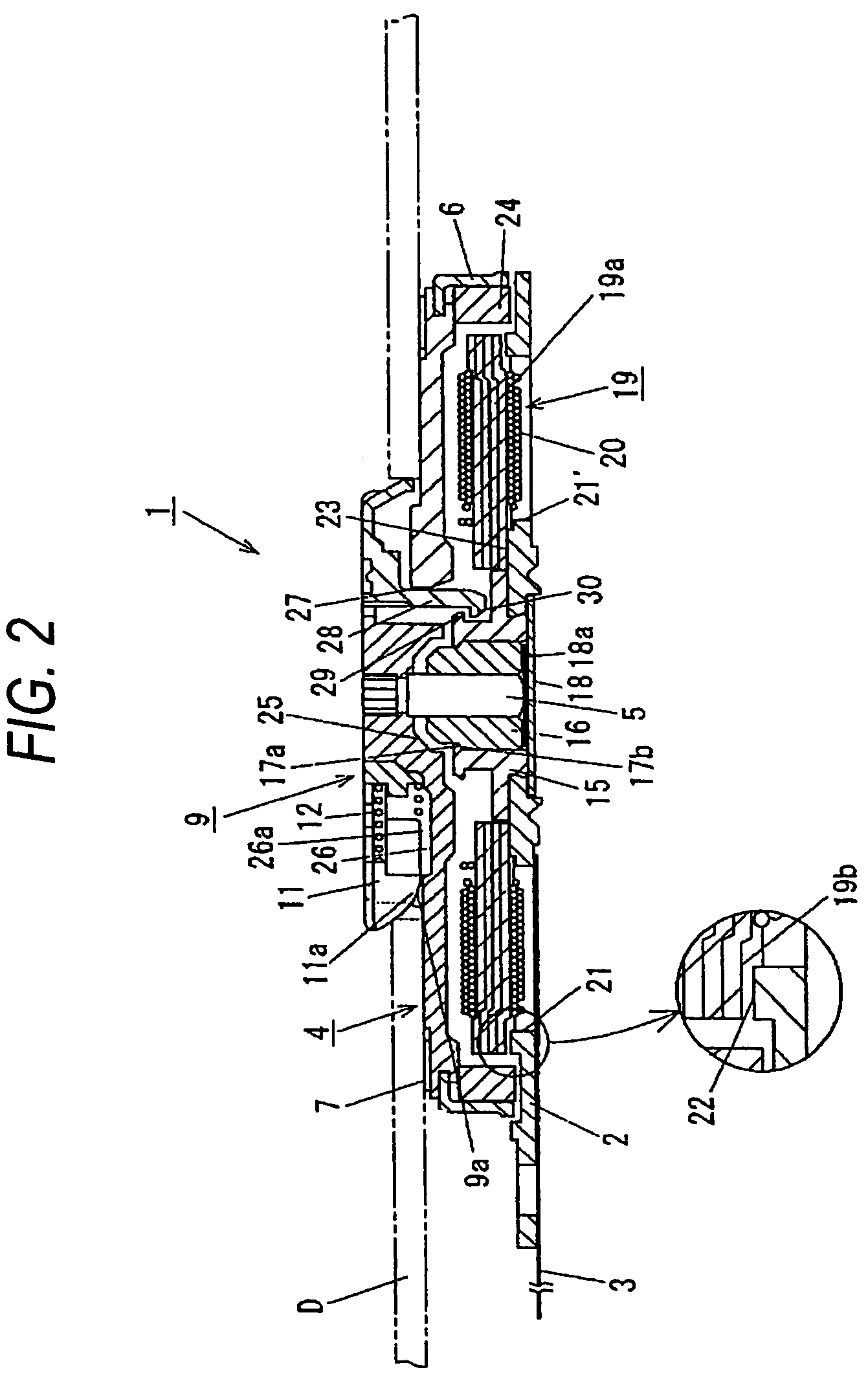
[0136]FIG. 1 is a plan view of a disk drive according to Embodiment 1 of the invention, and FIG. 2 is a sectional view taken along the line A-A in FIG. 1 and viewed in a direction indicated by arrows attached to the line.

[0137]In the figures, reference numeral 1 denotes a disk drive according to Embodiment 1 of the invention, 2 a base portion, 2a a mounting raised portion via which the disk drive 1 is mounted in a housing where to house the disk drive 1, the mounting raised portion being provided in a plural number, 2b a mounting hole formed substantially at a central portion of the mounting raised portion 2a, 2c a mounting surface formed on an upper side of the mounting hole 2b, 3 a circuit board on which an electronic element for driving a motor is mounted, and which includes a circuit board for supplying an electricity to the electronic element and an exchanging an signal, provided to ex...

embodiment 2

[0169]FIG. 7(a) is a sectional view which shows a main part of a disk drive according to Embodiment 2 of the invention, and FIG. 7(b) is an enlarged sectional view which shows a main part of a bearing portion.

[0170]In FIGS. 7(a), 7(b), reference numeral 1a denotes a disk drive according to Embodiment 2, 2 a base portion, 4 a turntable, 5 a spindle, 6 a yoke, 9 a disk holding portion, 15 a bearing holding portion, 16 a bearing portion, 18 a thrust plate, 18a a thrust bearing sheet, 19 a stator, 24 a magnet, and D a disk, and like reference numerals are imparted to constituent components including these which are like to those described with reference to Embodiment 1, and the description thereof will be omitted.

[0171]Here, reference numeral 35 denotes an annular spindle attracting magnet which is provided on a side of the bearing portion 16 which lies to a side of the base portion 2 in such a manner as to surround circumferentially a distal end portion of the spindle 5 which lies to t...

embodiment 3

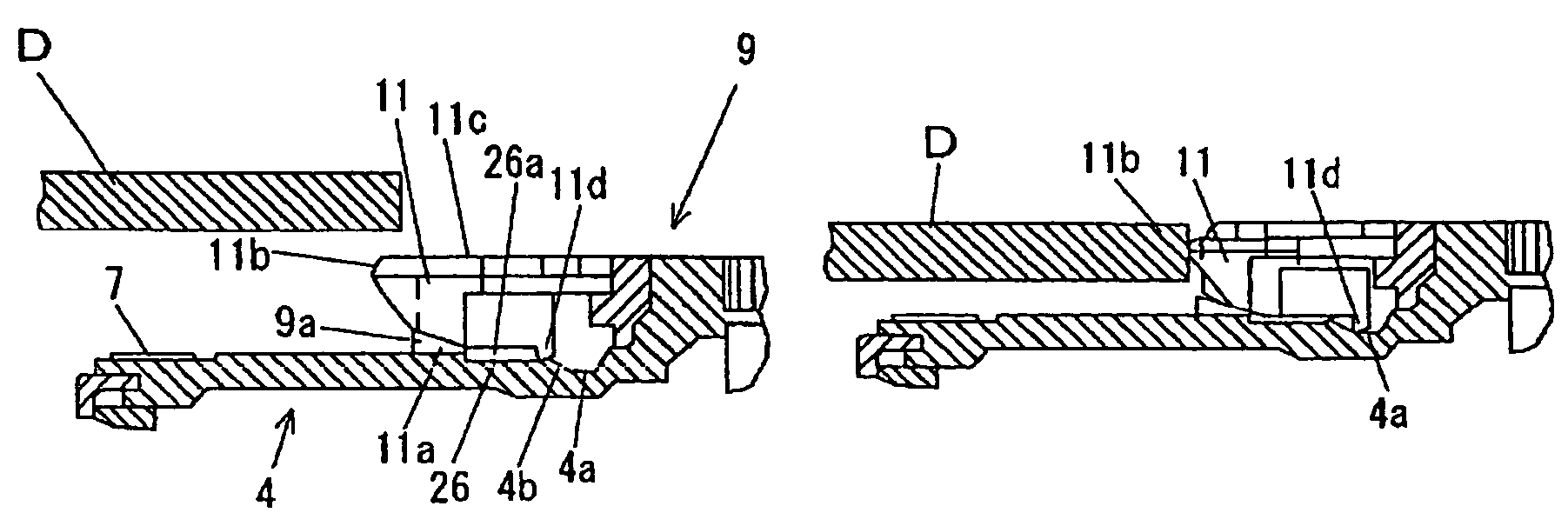
[0174]FIG. 8 is a sectional view which shows a main part of a disk drive according to Embodiment 3 of the invention.

[0175]In FIG. 8, reference numeral 1b denotes a disk drive according to Embodiment 3, 4 a turntable, 7 a slip preventive material, 9 a disk holding portion, 11 a disk holding claw, 12 a spring portion, and reference character D denotes a disk, and like reference numerals are imparted to constituent components including these which are like to those described with reference to Embodiment 1, and the description thereof will be omitted.

[0176]In addition, since the configuration of the disk holding portion 9 is similar to what is shown in FIG. 1 which is described with reference to Embodiment 1, the same figure will also be used in the following description.

[0177]Here, the disk holding portion 9 includes a plurality of sliding groove portions 10 formed thereon in such a manner as to extend from an outer circumferential portion to a central portion thereof, disk holding cla...


PUM

PropertyMeasurementUnit
thicknessaaaaaaaaaa
circumferenceaaaaaaaaaa
mechanical strengthaaaaaaaaaa

Abstract

A disk drive 1 of the invention has through holes 27 formed in a turntable 4 in such a manner as to surround circumferentially a spindle 5, dislodgement preventive portions 28 provided to extend from a lower surface of a disk holding portion 9 towards a base portion 2 through the through holes 27, a hook locking portion 29 formed on an outer circumferential wall of a bearing holding portion 15 and hook portions 30 formed on distal end portions of the dislodgement preventive portions 28 which lie to a side of the base portion 2. In addition, the base portion 2 of the disk drive 1 of the invention includes a plurality of openings into which respective coils 20 are partially inserted and is configured such that an outer circumferential portion of a stator core 19a and the base portion 2 are spaced apart from each other at a predetermined interval.

Description

BACKGROUND OF THE INVENTION[0001]1. Field of the Invention[0002]The present invention relates to a disk drive which drives to rotate a disk such as a CD and a DVD which are used as recording media.[0003]2. Description of the Related Art[0004]In recent years, when reading data from and writing data onto disks such as CDs and DVDs which are used as recording media, a method is generally used in which a pickup or read / write head is caused to glide in a radial direction while rotating a disk. As this occurs, a disk drive such as shown in (JP-A-2003-348812) is used as a device for driving to rotate the disk.[0005]Hereinafter, a conventional disk drive will be described using FIG. 15.[0006]FIG. 15 is a sectional view of a main part of a conventional disk drive.[0007]In FIG. 15, reference numeral 100 denotes a conventional disk drive, 101 a base portion, 102 a cylindrical bearing holding portion provided substantially at a central portion on an upper surface of the base portion, 103 a bear...

Claims


Application Information

Patent Timeline
Patent Type & Authority Patents(United States)
IPC IPC(8): G11B19/20
CPCG11B17/0282G11B19/2009
Inventor TOYOKAWA, SHOKICHIKUDO, MASATO
Owner PANASONIC CORP
Why Eureka
Try Eureka