Organic light emitting device and method for manufacturing the same

a light-emitting device and organic technology, applied in the direction of solid-state devices, electric lighting sources, electric light sources, etc., can solve the problems of power consumption increase, brightness, contrast ratio, viewing angle limitation, etc., to reduce thickness and weight of the device, increase light efficiency, and reduce manufacturing costs

Active Publication Date: 2012-12-13
LG DISPLAY CO LTD
View PDF1 Cites 18 Cited by
  • Summary
  • Abstract
  • Description
  • Claims
  • Application Information

AI Technical Summary

Benefits of technology

[0032]An advantage of the embodiments of the present invention is to provide an organic light emitting device and a method for manufacturing the same, which can reduce thickness and weight of the device by sealing an OLED with a metal foil.
[0033]Another advantage of the embodiments of the present invention is to provide an organic light emitting device and a method for manufacturing the same, which can reduce the manufacturing cost by sealing an OLED with a metal foil.
[0034]Still another advantage of the embodiments of the present invention is to provide an organic light emitting

Problems solved by technology

However, the liquid crystal display device requires a back light as a separate light source and has also technical limitations in brightness, contrast ratio, and viewing angle.
Accordingly, power consumption is increased and there is limitation in resolution.
However, the OLED 20 of the related art, which sh

Method used


Image

  • Organic light emitting device and method for manufacturing the same
  • Organic light emitting device and method for manufacturing the same
  • Organic light emitting device and method for manufacturing the same

Examples


Embodiment Construction

[0048]Reference will now be made in detail to the exemplary embodiments of the present invention, examples of which are illustrated in the accompanying drawings. Wherever possible, the same reference numbers will be used throughout the drawings to refer to the same or like parts.

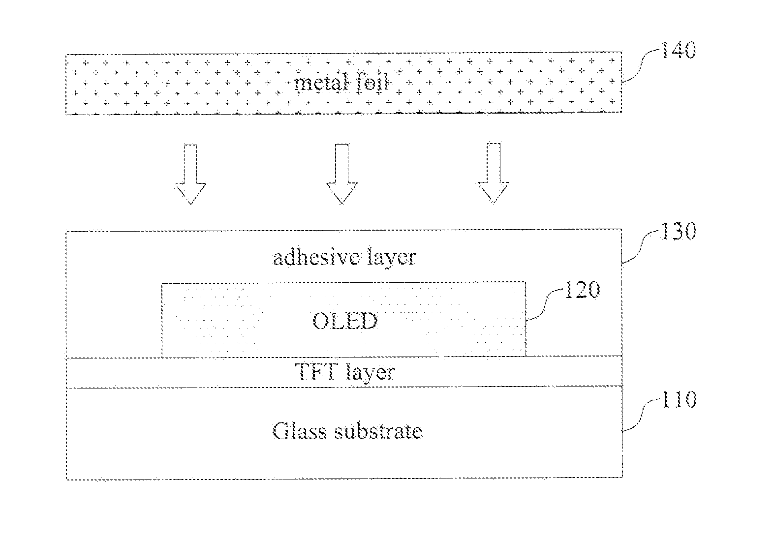
[0049]Hereinafter, an organic light emitting device and a method for manufacturing the same according to the embodiments of the present invention will be described with reference to the accompanying drawings.

[0050]In the description of the embodiments according to the present invention, the disclosure that a structure is formed ‘on or above’ and ‘below or under’ another structure should be interpreted to include the disclosure that a third structure is interposed between the structures as well as the disclosure that the structures are in contact with each other. The term “substantially the same” is interpreted to include that the metal foil has the thermal expansion coefficient substantially equal or similar...


PUM


Abstract

An organic light emitting device and a method for manufacturing that same are discussed, which can reduce thickness and weight of the device as well as the manufacturing cost. The organic light emitting device includes according to an embodiment an organic light emitting diode (OLED) formed on a glass substrate; an adhesive layer formed to cover the OLED; and a metal foil formed on the adhesive layer to seal the OLED and bonded to the glass substrate, wherein the metal foil is formed of an alloy having the same or substantially the same thermal expansion coefficient as that of the glass substrate.

Description

CROSS REFERENCE TO RELATED APPLICATIONS[0001]This application claims priority under 35 U.S.C. §119 to the benefit of the Korean Patent Application No. 10-2011-0055238, filed on Jun. 8, 2011, which is hereby incorporated by reference for all purposes as if fully set forth herein.BACKGROUND OF THE INVENTION[0002]1. Field of the Invention[0003]Embodiments of the present invention relate to an organic light emitting device and a method for manufacturing the same, which can reduce the manufacturing cost as well as thickness and weight of the device.[0004]2. Discussion of the Related Art[0005]A liquid crystal display device has been widely used as a flat panel display device. However, the liquid crystal display device requires a back light as a separate light source and has also technical limitations in brightness, contrast ratio, and viewing angle.[0006]Recently, an organic light emitting device, which does not require a separate light source due to its self light-emission and has relati...

Claims


Application Information

Patent Timeline
IPC IPC(8): H01L33/52H01L33/48
CPCH01L51/5243H01L2251/55H01L51/5246H10K50/8423H10K2101/00H10K50/84H10K71/00H05B33/04H10K50/8426H10K50/844
Inventor SHIN, YOUNGHOONAHN, BYUNGCHULLEE, JAEHYUKTAK, YOONHEUNGKIM, MYUNGSEOPKYOUNG, SEUNG
Owner LG DISPLAY CO LTD
Why Eureka
Try Eureka