

Seat reclining apparatus
a seat and reclining technology, applied in the direction of pedestrian/occupant safety arrangements, vehicle components, vehicle arrangements, etc., can solve the problems of not easy to become unsmooth, and the position of the second cam is becoming distorted
- Summary
- Abstract
- Description
- Claims
- Application Information
AI Technical Summary
Benefits of technology
Problems solved by technology
Method used
Image

Examples
Embodiment Construction
[0053]An embodiment of the present invention will be hereinafter discussed with reference to FIGS. 1 through 25. Directions described in the following description are defined based on the directions of arrows shown in the drawings. In the following description, the term “inner peripheral side” refers to the center side of a base plate 27 of the seat reclining apparatus 25 and the term “outer peripheral side” refers to the radially opposite side of the base plate 27 from the center side thereof.
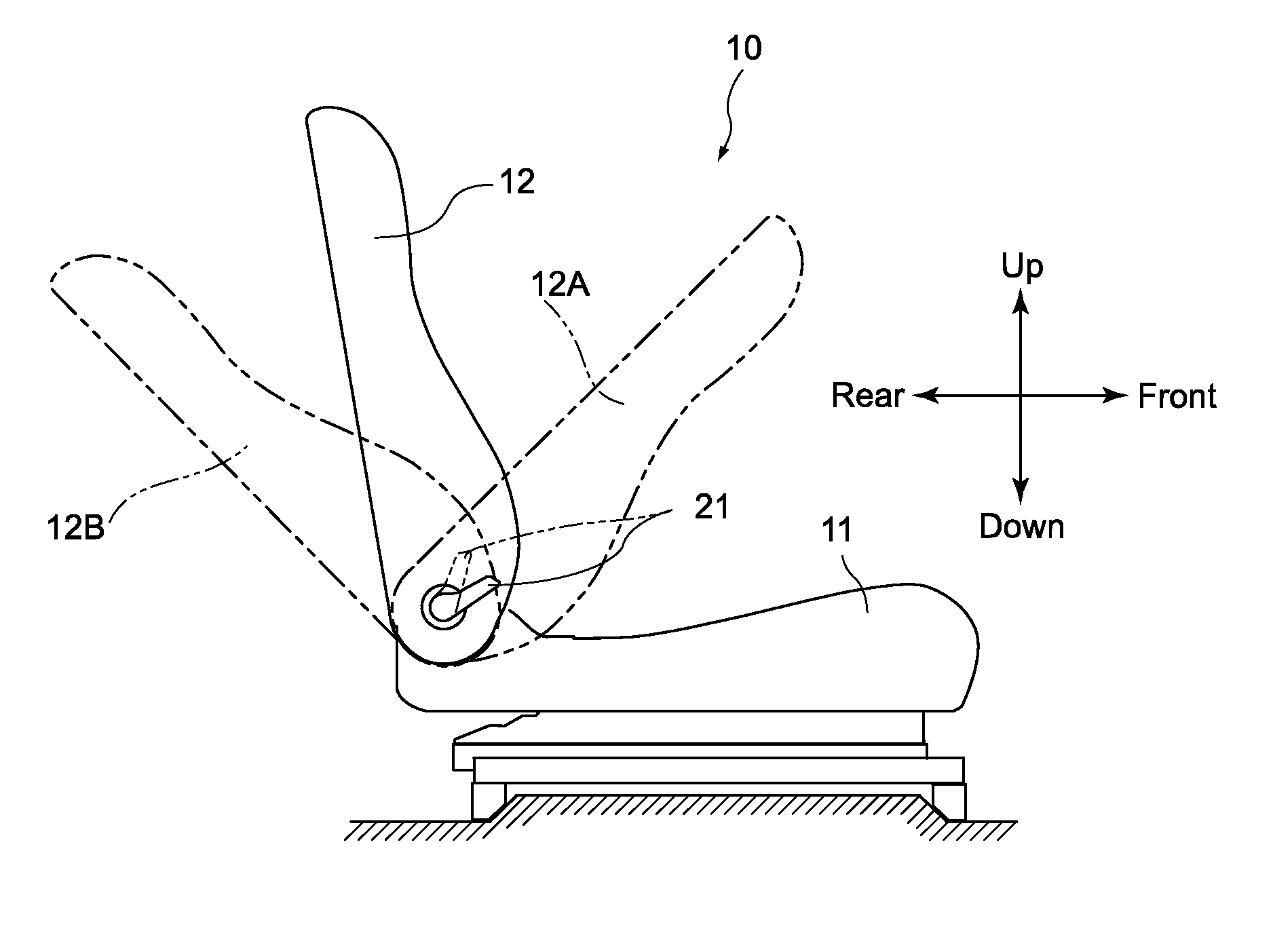
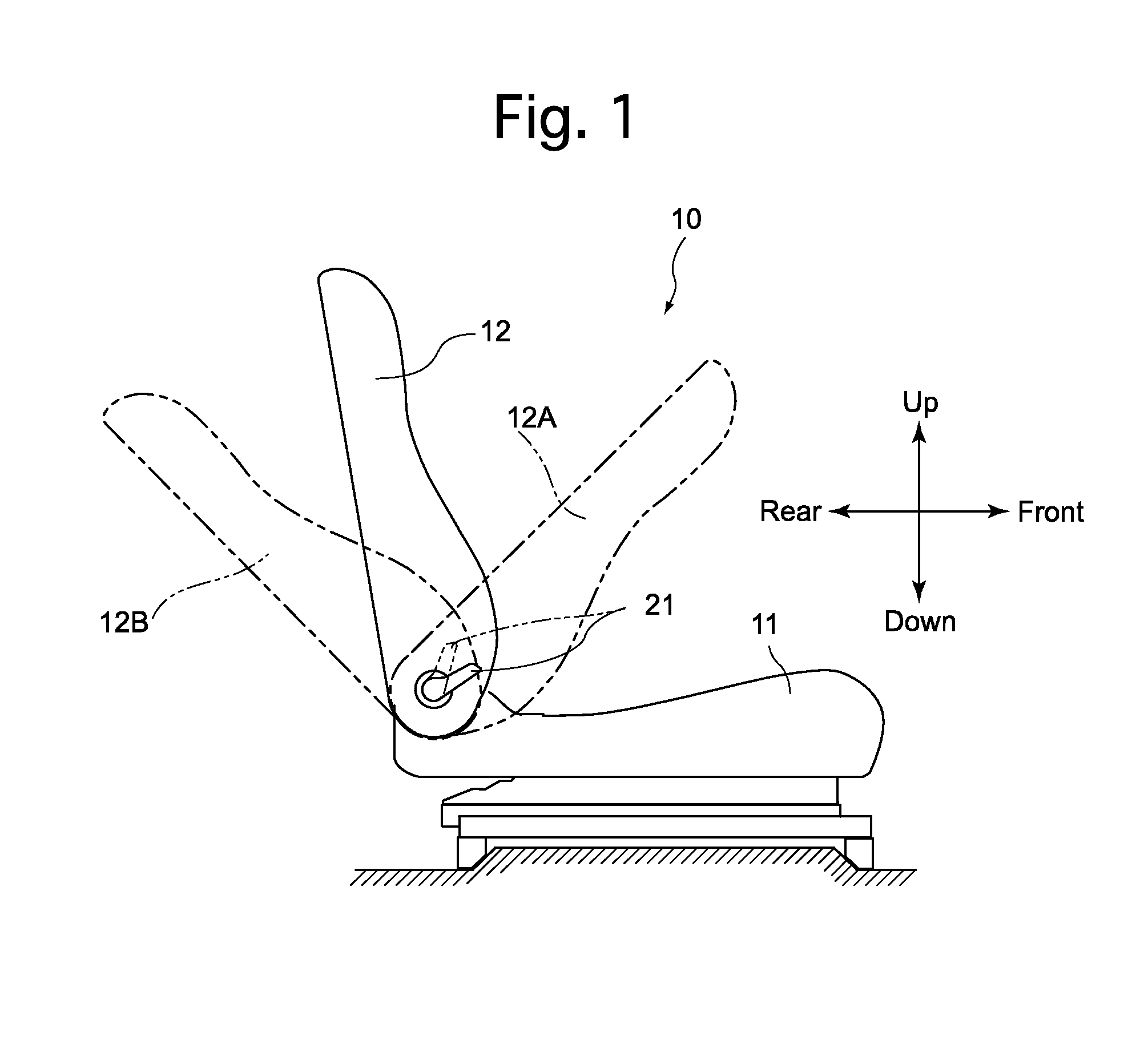
[0054]A vehicle seat 10 shown in FIG. 1 is a right-side seat and is provided with a seat cushion 11 which is supported by a vehicle interior floor of a vehicle (e.g., an automobile) via a seat rail, and a seatback 12 which is rotatable relative to (pivoted at) the rear of the seat cushion 11. A pair of left and right seat cushion frames, made of metal, are installed inside the seat cushion 11 in a fixed state. Each seat cushion frame is a plate-shaped member extending in the forward / rearward d...
PUM
 Abstract
Description
Claims
Application Information