Landing gear drive systems

Active Publication Date: 2014-09-04
AIRBUS OPERATIONS LTD
View PDF0 Cites 20 Cited by
  • Summary
  • Abstract
  • Description
  • Claims
  • Application Information

AI Technical Summary

Benefits of technology

[0027]An advantage of the sprocket-roller arrangement is that it is more tolerant of wheel deformation than meshing toothed gear arrangements. Landing gear wheels are subject to high loads and consequential deformation during ground taxiing, and a driven gear fixed to the wheel will inevitably deform in response to such wheel deformation. Meshing toothed gears are intolerant of such deformation and a typical toothed rim gear may need to be isolated from the wheel via bearings, a flexible interface, or similar. In contrast, the sprocket and roller arrangement of the present invention is able to tolerate the deformation without such modification. Providing the sprocket as the drive pinion and the series of rollers as the driven gear serves to maximise the number of rollers, and therefore serves to minimise the wear per

Problems solved by technology

Landing gear wheels are subject to high loads and consequential deformation during ground taxiing,

Method used


Image

  • Landing gear drive systems
  • Landing gear drive systems
  • Landing gear drive systems

Examples


Embodiment Construction

)

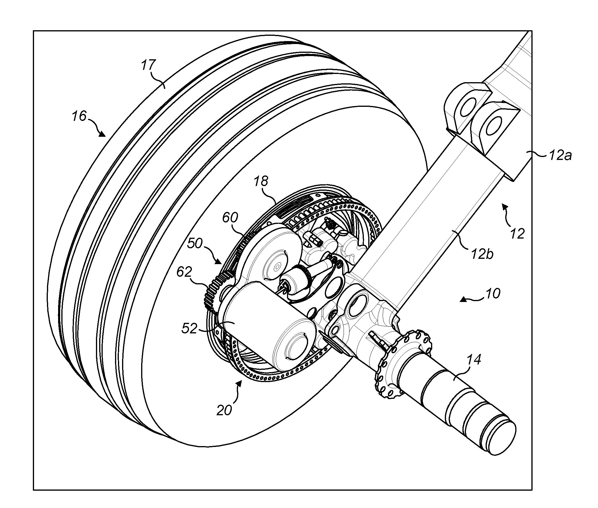
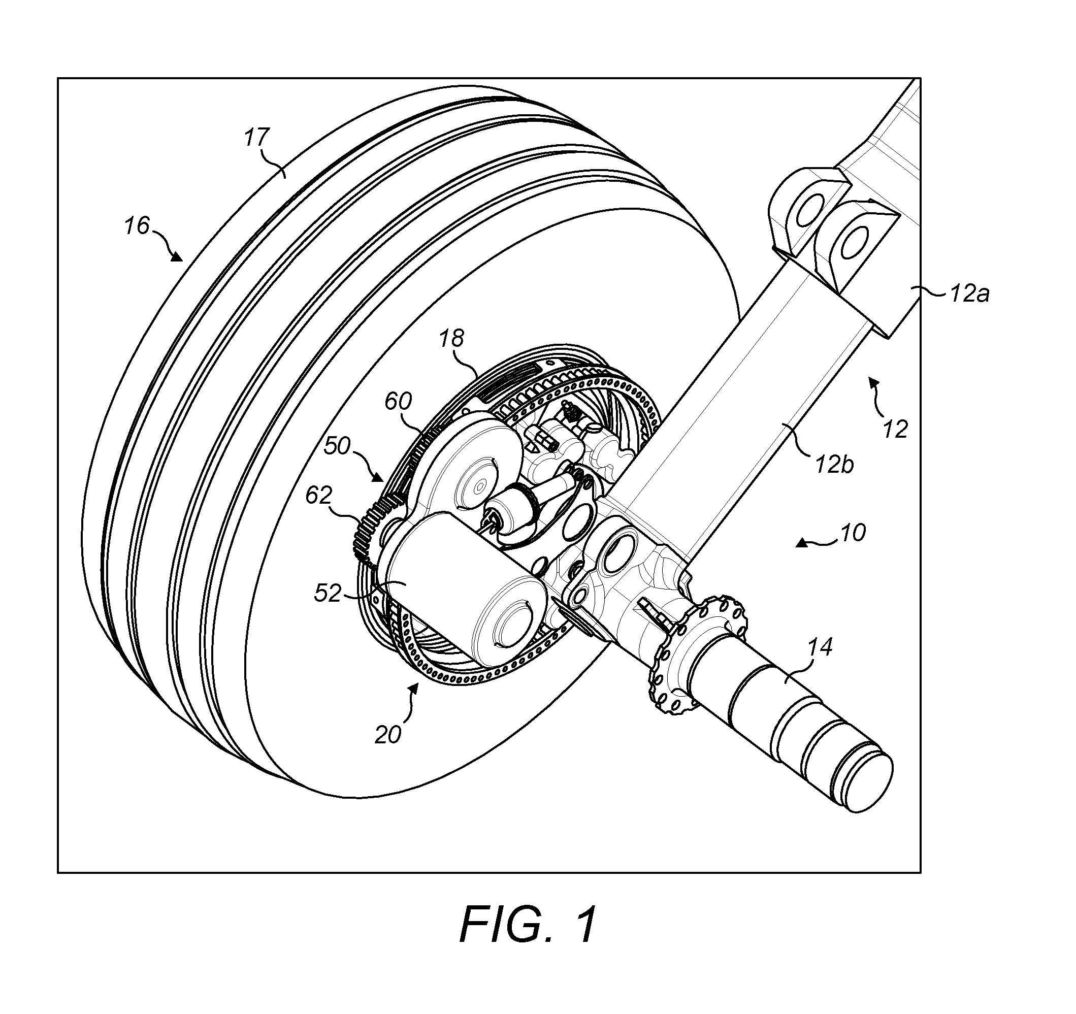
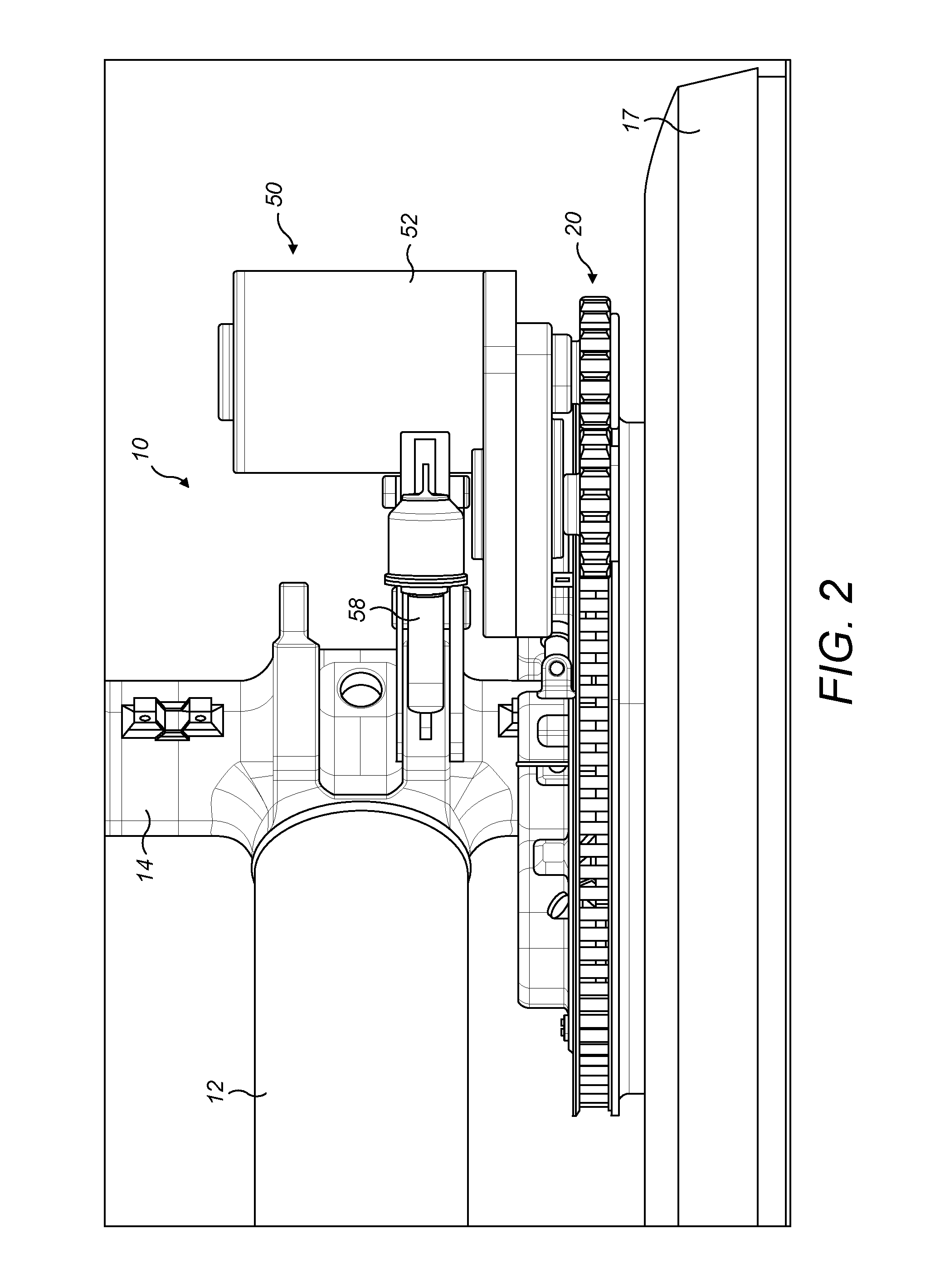
[0048]A first embodiment of the invention is shown in FIGS. 1 to 8. In the illustrated embodiment the landing gear has two wheels, but the principles of the embodiment may be applied to landing gear with four or more wheels. The embodiment shows a main landing gear (i.e. a landing gear attached to wing structure or fuselage structure in the region of the wings), since the weight supported by the main landing gear is considered to provide the best traction between the wheels and the ground to enable reliable aircraft ground taxiing. However, the drive system of the present invention may alternatively be applied to a nose landing gear (i.e. a steerable landing gear towards the nose of the aircraft).

[0049]The landing gear 10 includes a telescopic shock-absorbing main leg 12, including an upper telescopic part 12a (main fitting) and a lower telescopic part 12b (slider). The upper telescopic part 12a is attached to the aircraft fuselage or wing (not shown) by its upper end (not shown). ...


PUM


Abstract

A drive system for rotating a wheel of an aircraft landing gear includes a motor operable to rotate a first drive pinion via a first drive path and a driven gear adapted to be fixed to the wheel. The drive system has a first configuration in which the first drive pinion is capable of meshing with the driven gear to permit the motor to drive the driven gear via the first drive path. One of the first drive pinion and the driven gear comprises a first sprocket and the other of the first drive pinion and the driven gear comprises a series of rollers arranged to form a ring. Each roller being rotatable about a roller axis at a fixed distance from an axis of rotation of the first drive pinion or driven gear, respectively.

Description

FIELD OF THE INVENTION[0001]The present invention relates to drive systems for rotating one or more wheels of an aircraft landing gear for the purposes of ground taxiing and / or spin-up prior to landing.BACKGROUND OF THE INVENTION[0002]Aircraft are required to ground taxi between locations on airfields. An example is taxiing between a runway and the location (e.g. terminal gate) at which the aircraft's passengers are to board or disembark. Typically, such taxiing is achieved by using the thrust from the aircraft's engines to propel the aircraft forwards so that the landing gear wheels are caused to rotate. Since ground taxi speeds are necessarily relatively low, the engines must be run at a very low power. This means that there is a relatively high fuel consumption as a result of the poor propulsion efficiency at this low power. This leads to an increased level of both atmospheric and noise pollution locally around airports. Moreover, even when the engines are run at low power it is ...

Claims


Application Information

Patent Timeline
IPC IPC(8): B64C25/40
CPCB64C25/405Y10T74/19684Y02T50/80F16H1/06F16H55/10B64C25/40B64C25/50B64C25/34
Inventor DIDEY, ARNAUD
Owner AIRBUS OPERATIONS LTD
Why Eureka
Try Eureka