Electrochemical device

a technology of electrochemical devices and film packages, applied in the direction of cell components, cell components, jackets/cases materials, etc., can solve the problems of electrochemical devices being susceptible to various failure modes, electrochemical devices being susceptible to similar or same failure modes, and excess heat expansion and deformation of film packages. , to achieve the effect of suppressing heat transfer, preventing film package failure, and preventing excessive heat expansion and deformation

Inactive Publication Date: 2013-06-04
TAIYO YUDEN KK
View PDF15 Cites 4 Cited by
  • Summary
  • Abstract
  • Description
  • Claims
  • Application Information

AI Technical Summary

Benefits of technology

[0015]The armor (the protective outer package) of this device is in tight contact with a surface of a film package and covers an entire film package. Also the armor is in tight contact with a surface of each terminal and covers a part of the surface of the terminal. Because of this, excessive heat expansion and deformation of the film package can be prevented even if the heat in the reflow soldering is transferred to the film package through an armor (a protective outer package). This makes it possible to substantially prevent failure of the film package due to a leak of the electrolyte and breaking of the film package. Furthermore, the armor (the protective outer package) can suppress the heat transfer to the film package. Therefore, the armor can alleviate effects of the heat on the film package and its interior during reflow soldering.

Problems solved by technology

However, in conventional electrochemical devices having a film package, the film package is not suitable for reflow soldering using lead-free solder.
Because of the expansion and the deformation, the electrochemical devices are susceptible to various failures, such as leaking of the electrolyte or breaking of the film package.
But, because the case does not prevent the film package from the heat expansion and the deformation, the electrochemical device is susceptible to similar or same failure modes as described above.

Method used


Image

  • Electrochemical device
  • Electrochemical device
  • Electrochemical device

Examples


first modification

[0047]FIG. 5 is a cross-sectional view of an electric double-layer capacitor. The cross-sectional view is taken in the same manner as in FIG. 3.

[0048]This electric double-layer capacitor 10-1 has a different structure from that of the electric double-layer capacitor 10 shown in FIGS. 1-4 in that the vertical center SL1 of the film package 14 is shifted downwardly from the vertical center SL2 of the armor 16-1 by a predetermined amount OS. In more detail, the thickness t2 of a portion of the armor 16-1 that covers the principal surface (the top surface, for example) of the film package 14 is made larger than the thickness t1 of a portion of the armor 16-1 that covers the side of another principal surface (the bottom surface, for example) of the film package 14. Hence, the electric double-layer capacitor 10-1 is made asymmetric in the vertical direction. The rest of the structure is the same as that of the electric double-layer capacitor 10 shown in FIGS. 1-4. Thus the same notations ...

second modification

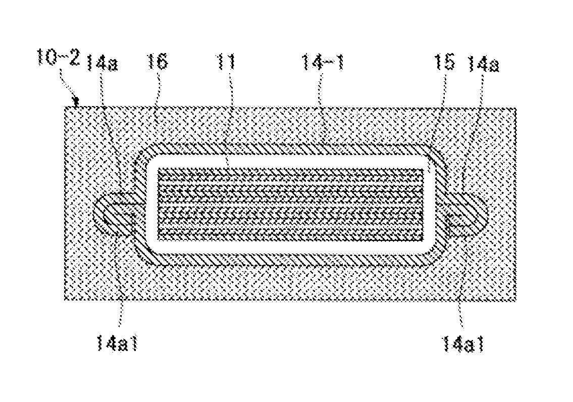
[0050]FIG. 6A shows a second modification of the embodiment. This figure is a cross-sectional view of an electric double-layer capacitor taken in the same manner as in FIG. 3. An electric double-layer capacitor 10-2 shown in the figure is formed in a similar way as the aforementioned electric double-layer capacitor in a sense that the side edges of the two films of the film package 14-1 are heat-sealed for encapsulation to constitute the heat seal part 14a

[0051]This electric double-layer capacitor 10-2 has a different structure from that of the electric double-layer capacitor 10 shown in FIGS. 1-4 in that a folded part 14a1 is formed in each of the heat-seal parts 14a. Because the rest of the structure is the same as that of the electric double-layer capacitor 10 shown in FIGS. 1-4, the same notations are used for the same or like components, and the descriptions therefor are not repeated here.

[0052]In the electric double-layer capacitor 10-2, by having the folded part 14a1, the st...

third modification

[0054]FIG. 7 shows a third partially modified embodiment. This figure is a cross-sectional view of an electric double-layer capacitor, taken in the same manner as in FIG. 3.

[0055]An electric double-layer capacitor 10-3, which is shown in FIG. 7, has a structure different from that of the electric double-layer capacitor 10 shown in FIGS. 1-4 in that a film package 14-2 has dimensions larger than the electrodes part 11 in width and length such that there is a distance L between the side wall of the electrodes part 11 and the farthest inner wall of the film package 14-2 that faces the side of the electrodes part. Because the rest of the structure is the same as that of the electric double-layer capacitor 10 shown in FIGS. 1-4, the same notations are used for the same or like parts, and the descriptions therefor are not repeated here.

[0056]In the electric double-layer capacitor 10-3, because of the distance L between the side wall of the electrodes part 11 and the farthest inner wall of...


PUM

PropertyMeasurementUnit
temperatureaaaaaaaaaa
thermal conductivityaaaaaaaaaa
thicknessaaaaaaaaaa

Abstract

An electrochemical device capable of being mounted by soldering includes a film package made of a film; an electrodes part encapsulated together with an electrolyte in said film package; a pair of terminals, one end of each terminal being connected to said electrodes part and another end of each terminal being exposed to an exterior of said film package; and an armor in contact with a substantially entire surface of said film package and in contact with partial surfaces of the exposed ends of said pair of terminals, respectively, to encapsulate said film package, said armor exposing remaining portions of said pair of terminals to an exterior of the armor.

Description

[0001]This application hereby incorporates by reference a Japanese patent application No. 2008-022908, filed in Japan on Feb. 1, 2008.BACKGROUND OF THE INVENTION[0002]1. Field of the Invention[0003]The present invention relates to an electro-chemical device, which has a film package. More particularly, the present invention relates to an electro-chemical device capable of being processed with reflow soldering using a lead-free solder.[0004]2. Description of the Related Art[0005]A film package is used in various electro-chemical devices, such as an electric double-layer capacitor, a Lithium ion capacitor, a redox capacitor, and a Lithium ion battery.[0006]The schematic structure of an electric double-layer capacitor, which is representative of these electrochemical devices, is explained. In an electric double layer capacitor in general, an electrodes part is encapsulated with an electrolyte covered by a package, which is formed of laminated films. The electrodes part is formed by sta...

Claims


Application Information

Patent Timeline
Patent Type & Authority Patents(United States)
IPC IPC(8): H01M2/00H01M50/117H01M50/119H01M50/121H01M50/124H01M50/143H01M50/172
CPCH01G9/155H01G11/12H01G11/18H01G11/74H01G11/78H01M2/0257H01G9/10H01M2/06H01M2/1094H01M2/22H01G9/016Y02E60/13H01M2/0287Y02E60/10H01M50/124H01M50/172H01M50/24H01M50/528H01M50/121H01M50/117H01M50/143H01M50/119
Inventor ISHIDA, KATSUEIYAWATA, KAZUSHIHAGIWARA, NAOTOKOBAYASHI, MOTOKI
Owner TAIYO YUDEN KK
Why Eureka
Try Eureka