
Disk array system and a method of avoiding failure of the disk array system

a technology of disk array system and disk array system, which is applied in the direction of error detection/correction, input/output to record carrier, instruments, etc., can solve the problems of reducing the possibility of data loss, wasting a long time in recovering data, and delay in the timing of data copying to the spare disk driv

Active Publication Date: 2005-05-26
GOOGLE LLC
View PDF13 Cites 123 Cited by
  • Summary
  • Abstract
  • Description
  • Claims
  • Application Information

AI Technical Summary

Benefits of technology

[0011] It is an object of the present invention to provide a disk array system which can transfer data from a disk drive in which occurrence of failure is anticipated to a spare disk drive in a safer manner than in the related art, and a method of avoiding failure of the disk array system. Another object of the invention to provide a disk array system in which possibility of occurrence of failure in a normal disk drive is reduced by reducing writing and reading to a normal disk drive other than the disk drive in which occurrence of failure is anticipated and a method of avoiding failure of the disk array system. Other objects of the invention will be apparent from description of embodiments described later.

Problems solved by technology

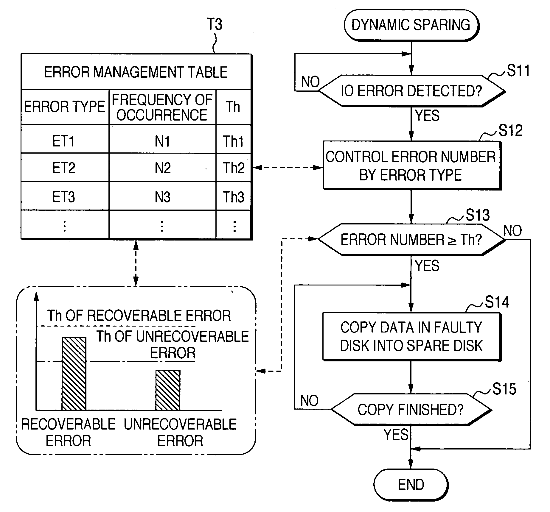
For example, by employing a redundant storage configuration known as RAID levels 1 to 6 in the disk array system, possibility of data loss decreases.
Therefore, timing to start data copy to the spare disk drive is delayed.
In addition, since data is recovered from a normal disk drive, it takes a long time to recover the data, and it also takes a long time until data copy is completed.
In addition, when any failure occurred successively in the part of another normal disk drive, data required for inverse operation cannot be obtained, and thus data of the faulty disk drive cannot be recovered.
Even with the normal disk drive, when read and write operation is repeated, possibility of occurrence of partial failure increases.
When two or more parts of information (data, parity) cannot be read, data cannot be recovered by inverse operation and thus unrecoverable data will be lost.

Method used


Image

  • Disk array system and a method of avoiding failure of the disk array system
  • Disk array system and a method of avoiding failure of the disk array system
  • Disk array system and a method of avoiding failure of the disk array system

Examples


first embodiment

1. First Embodiment

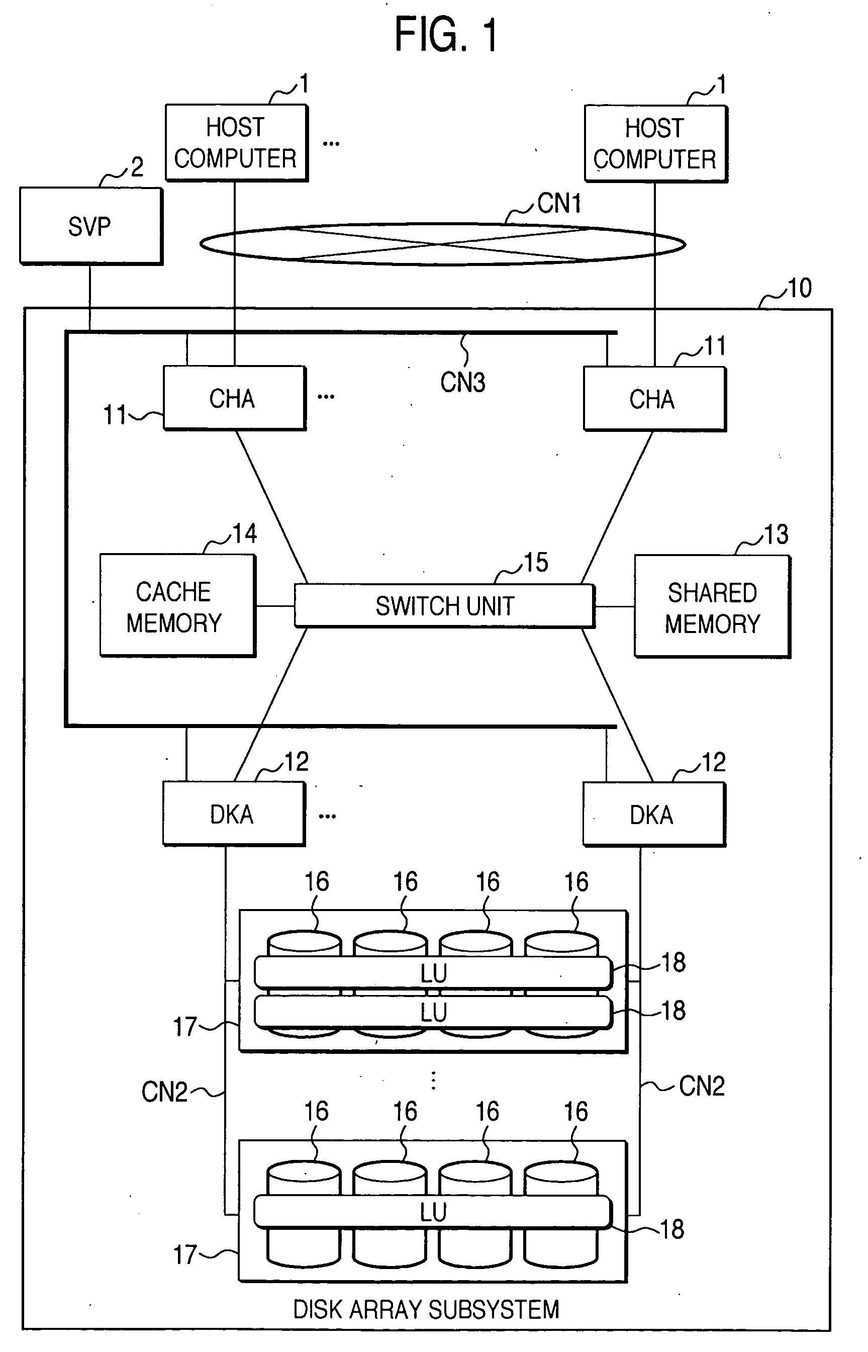
[0058] Referring to FIG. 1 to FIG. 9, an embodiment of the present invention will be described. FIG. 1 is a schematic block diagram showing a configuration of a disk array system 10.

[0059] The disk array system 10 is connected to a plurality of host computers 1 via a communication network CN1 so as to be capable of communicating with each other in both directions. The communication network CN1 here includes, for example, LAN (Local Area Network), SAN (Storage Area Network), and Internet. When using the LAN, data transfer between the host computer 1 and the disk array system 10 is executed according to TCP / IP (Transmission Control Protocol / Internet Protocol) protocol. When using the SAN, the host computer 1 and the disk array system 10 perform data transfer according to a fiber channel protocol. When the host computer 1 is a main frame, data transfer is performed according to the communication protocol, such as FICON (Fibre Connection: Registered Trademark), ESCON...

second embodiment

2. Second Embodiment

[0105] Referring to FIG. 10 to FIG. 13, the second embodiment of the present invention will be described. A characteristic of the present embodiment is that a logical volume is used as a data backup area during sparing. Another characteristic of the present embodiment is in that a journal file is used. FIG. 10 is an explanatory drawing schematically showing the entire operation of a method of avoiding failure according to the present embodiment. The outline of the entire operation is almost the same as the previous embodiment.

[0106] When occurrence of failure is anticipated in a certain disk drive 16, sparing for transferring the contents stored in the disk drive 16 in which occurrence of failure is anticipated into a spare disk drive 16(SP) is started (S61). When the sparing is started, at least one unused logical volume 18 is reserved for a data backup area (S62). This unused logical volume 18 is used as a work volume 18(W). What should be noted here is that t...

third embodiment

3.

[0126] Referring now to FIG. 14 to FIG. 18, a third embodiment will be described. A characteristic of the present embodiment is that a work disk is used as a data backup area.

[0127]FIG. 14 is a schematic explanatory drawing of an entire operation of a method of avoiding data failure according to the present embodiment. When occurrence of failure in a certain disk drive 16 (#4) is anticipated, data transfer to the spare disk drive 16(SP) is started (S121).

[0128] Upon start of this data transfer, at least one unused work disk drive 16(W) is reserved (S122). When a write request is issued from the host computer 1, the update data is stored in a work disk drive 16(W) (S123). The data stored in the work disk drive 16(W) is controlled by a differential management table T7 (S124).

[0129] When a read request is issued from the host computer 1, and if data to be read exists in a main disk drive 16, which is the original location of backupdate, the data is read out form the main disk driv...


PUM


Abstract

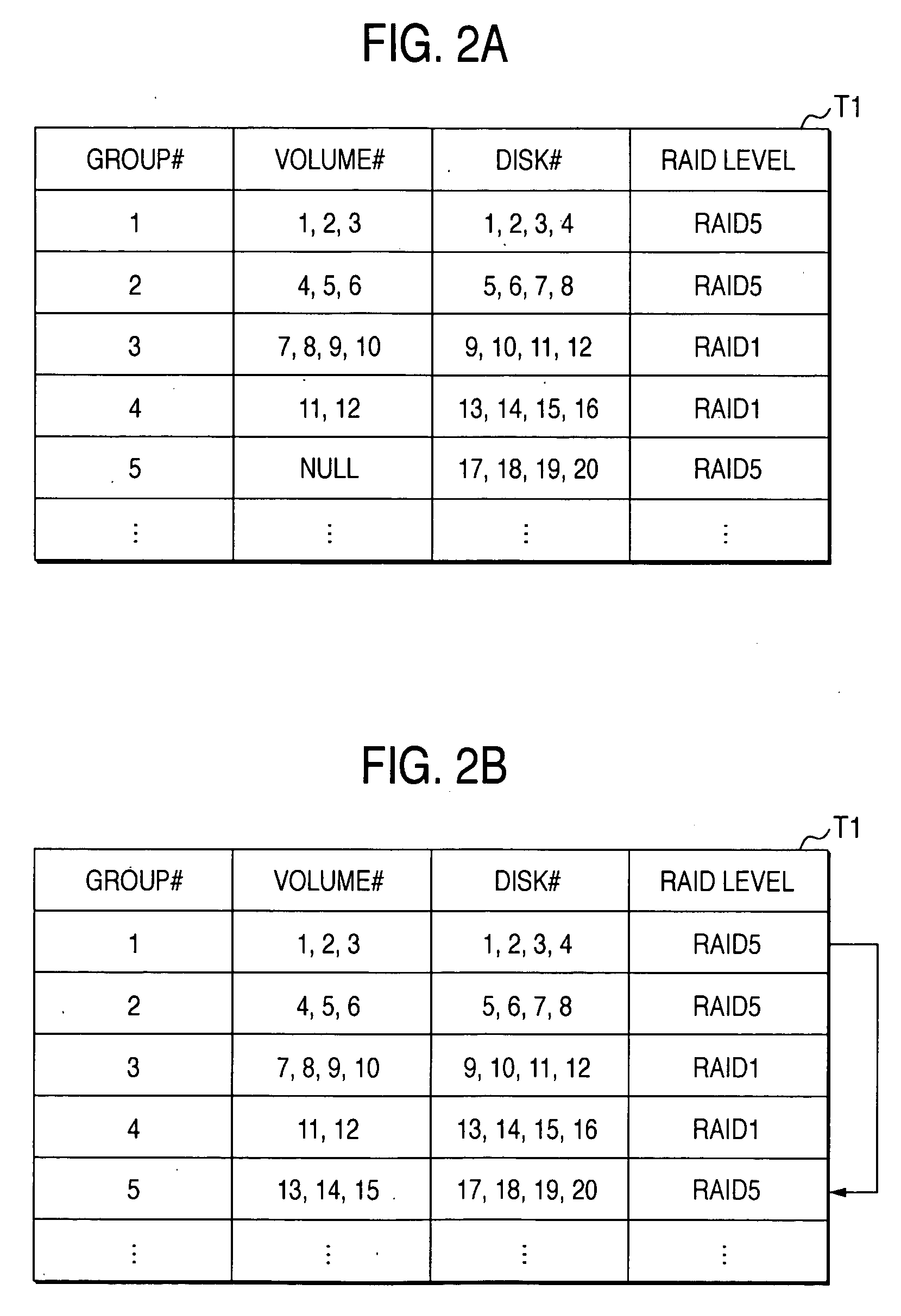
The invention is intended to reduce disk access during data transfer from a disk in which occurrence of failure is anticipated to a spare disk as much as possible so that occurrence of double-failure is prevented in advance. When occurrence of failure in a disk which configures a RAID group, contents stored in the disk is copied to the spared disk. Simultaneously, another RAID group is paired with the above described RAID group and a secondary volume is provided therein. A write request is directed to the secondary volume. A differential bitmap controls a update data. Data which is not updated is read out from the primary volume, and data which is already updated is read from the secondary volume. When data transfer is completed, contents stored in the secondary volume are copied to the primary volume.

Description

CROSS-REFERENCE TO RELATED APPLICATIONS [0001] This application relates to and claims priority from Japanese Patent Application No. 2003-395322, filed on Nov. 26, 2003, the entire disclosure of which is incorporated herein by reference. BACKGROUND OF THE INVENTION [0002] 1. Field of the Invention [0003] The present invention relates to a disk array system having a plurality of disk drives and a method of avoiding failure of the disk array system. [0004] 2. Description of the Related Art [0005] The disk array system, including a number of disk drives in an array, is configured based on RAID (Redundant Array of Independent Inexpensive Disks). A logical volume, which is a logical storage area, is formed on a physical storage area possessed by each disk device. A host computer can read and write desired data by issuing a write command or a read command of a predetermined format to the disk array system. [0006] Various defensive measures are taken for the disk array system in order to pr...

Claims


Application Information

Patent Timeline
Patent Type & Authority Applications(United States)
IPC IPC(8): G06F12/16G06F3/06
CPCG06F11/1092G06F11/008
Inventor AIZAWA, MASAKIKATSURAGI, EIJUFUKUOKA, MIKIOOKAMOTO, TAKEKI
Owner GOOGLE LLC
Learn More