Powered surgical instrument having locking systems and a clutch mechanism

a technology of locking system and clutch mechanism, which is applied in the direction of manufacturing tools, applications, and osteosynthesis devices, etc., can solve the problems of complex mechanical system of instruments, high cost, and high cost of surgical instruments, and achieve the effect of reducing the cost of surgical instruments

Inactive Publication Date: 2001-07-10
MICROAIRE SURGICAL INSTR
View PDF15 Cites 134 Cited by
  • Summary
  • Abstract
  • Description
  • Claims
  • Application Information

AI Technical Summary

Benefits of technology

It is a further object of the present invention to provide a battery pack mounting system that allows a user to easily mount and remove a battery pack from the housing of a surgical instrument.
It is still a further object of the present invention to provide a mechanism that limits the torque output of a drive shaft of a surgical instrument.
It is still another object of the present invention to provide a mechanism that prevents failure of a motor shaft of a surgical instrument during use thereof
The surgical instrument of the present invention further includes a clutch mechanism which prevents failure of the motor shaft. The clutch mechanism includes a clutch plate fixed to the drive shaft and communicating with the output shaft. In the preferred embodiment of the present invention, the clutch plate includes detents that communicate with preferably steel balls (or any other appropriate material) mounted to the output shaft. When a predetermined torque limit is exceeded, the ball bearings "slip" from the detents such that the drive shaft rotates freely with respect to the output shaft. When the predetermined torque limit is not exceeded, the ball bearings are contained within the detents and the drive shaft rotates the output shaft.
By using the surgical instrument of the present invention, the drive shaft may be locked so as to use the surgical instrument in a manual mode. This allows the user to have more control of the surgical instrument, such as, for example, to manually insert screws into bones during a bone fixation procedure. The surgical instrument of the present invention further allows the torque output to be limited which protects the motor shaft from exceptionally high torque conditions, and potential failure thereof. Also, the use of a robust and easy to use mounting system for the battery pack allows easy installation and removal of the same.

Problems solved by technology

It is well known in the art that these surgical instruments are very complex, yet delicate, instruments which must be used with the utmost care during a surgical procedure.
For example, many of these instruments have complex mechanical systems in order to retain the tool within a collet of the surgical instrument such that the tool is firmly retained therein during the surgical procedure.
It is well known, however, that many of these procedures may be complicated and time consuming.
For example, many of the collets currently used include a key and lock mechanism which is both cumbersome to use and time consuming to adjust.
However, these collet systems tend to allow the tool to slip during use thereof, posing a serious danger to both the patient and the surgeon (or other medical worker).
However, even though a drive mechanism may assist the surgeon during surgery, there are times during specific surgical procedures that may require the need for a manual surgical instrument.
For example, a surgeon may need to apply a large torque to properly place a screw in a bone during a bone fixation procedure, which cannot be performed with a powered tool because the powered surgical instrument is not designed for that particular torque.
This may pose a danger to the patient.
Needless to say, the failure of the motor shaft during a surgical procedure is quite dangerous and also renders the surgical instrument useless for future surgical procedures.
However, with complex mounting systems, such as, key and lock systems, it may be difficult for the surgeon to properly mount the battery onto the housing.
This is especially important in the case of battery failure during a surgical procedure such that the surgeon cannot readily and easily remove the failed battery and replace it with a new battery.
Also, it is important to ensure that the battery is properly mounted because it has been found that less complicated battery mounting systems do not adequately retain the battery on the housing of the surgical instrument during a surgical procedure.
This, of course, poses the problem of a surgical instrument power failure during a surgical procedure which may pose countless dangers to the patient.

Method used


Image

  • Powered surgical instrument having locking systems and a clutch mechanism
  • Powered surgical instrument having locking systems and a clutch mechanism
  • Powered surgical instrument having locking systems and a clutch mechanism

Examples


Embodiment Construction

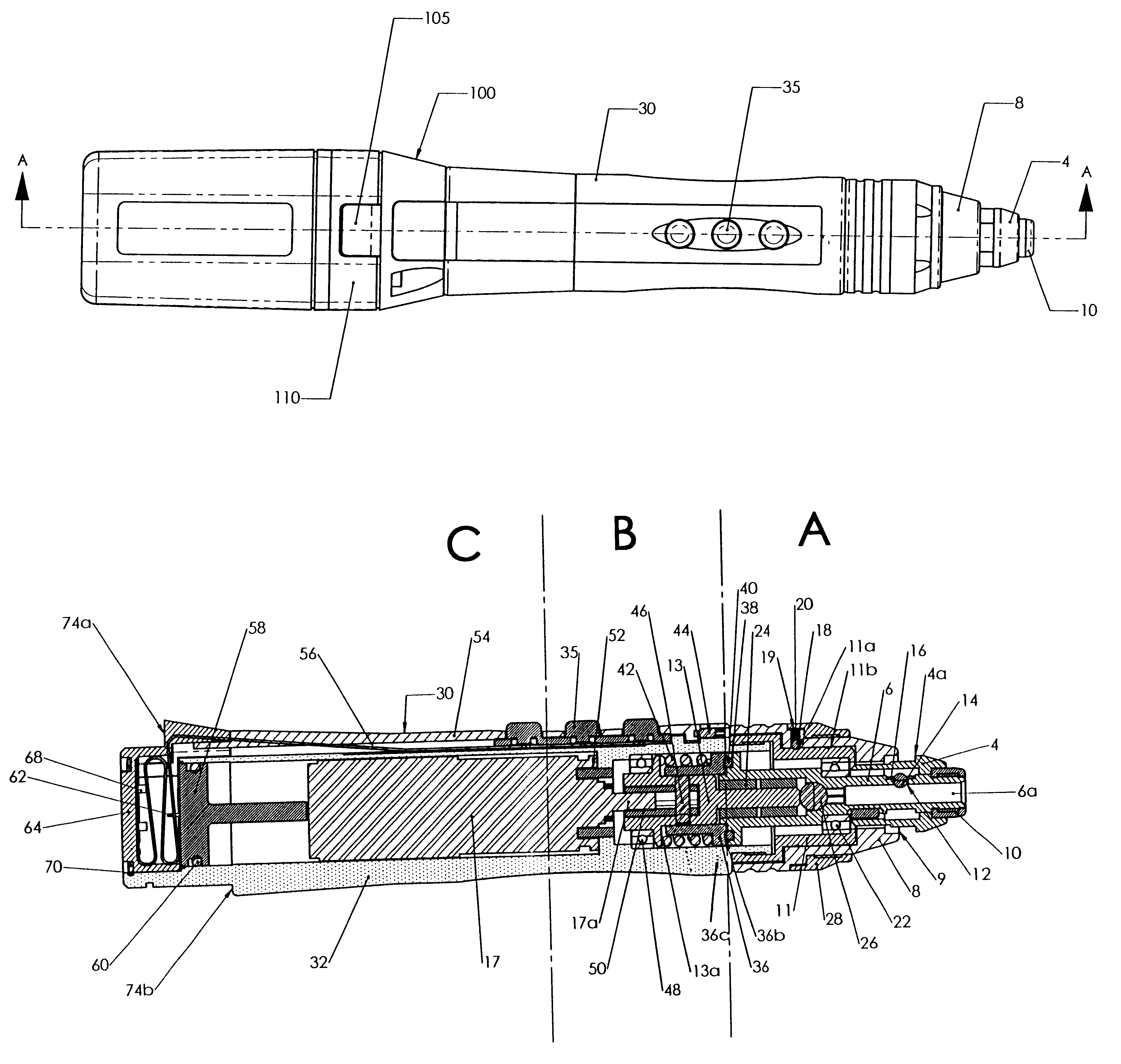
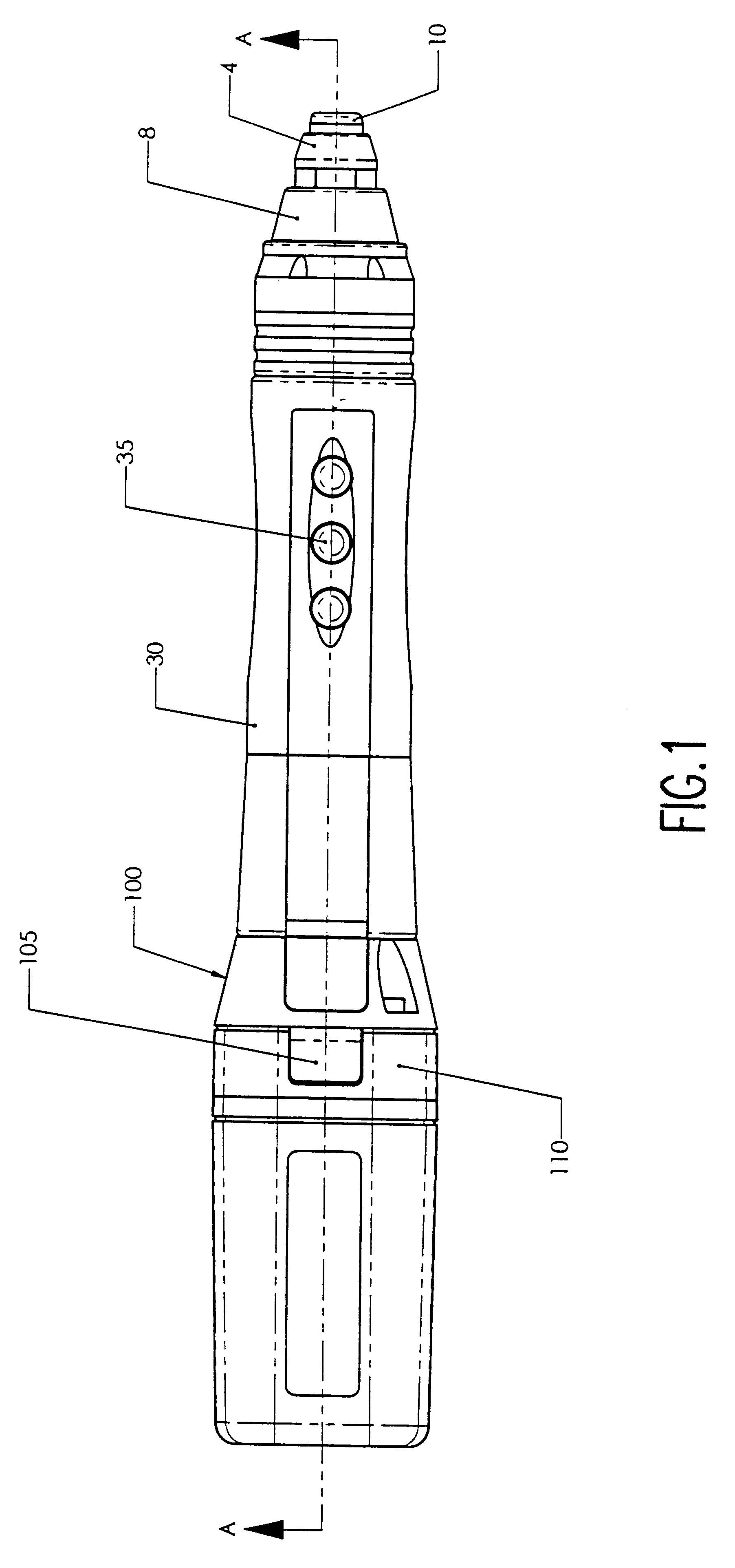
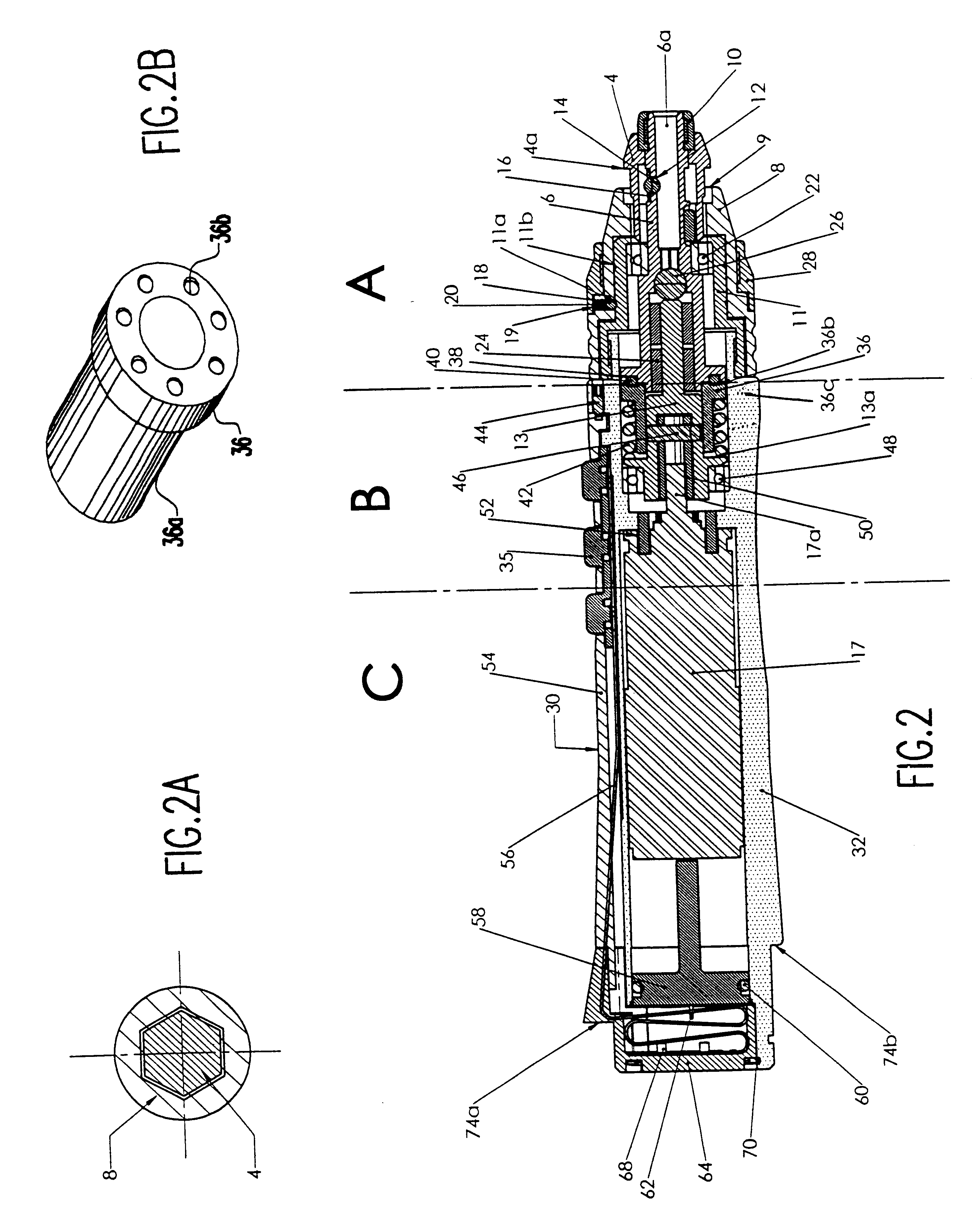
The present invention is directed to a surgical instrument having a locking system for mounting a battery pack thereon and for preventing rotation of the drive shaft in a manual mode, as well as a clutch mechanism to control the torque of the drive mechanism. In a preferred embodiment, the surgical instrument is designed for the insertion of small, bone fixation screws, and is applicable to oral, maxillofacial, cranial, spinal and orthopedic procedures. The surgical instrument of the present invention may equally be adapted for use as a manual or powered screwdriver, drill and the like, and is preferably designed for intermittent use (e.g., five seconds of run-time followed by five seconds of inactivity). However, the surgical instrument of the present invention may be used for other run times, and may also be used as a continuous run time surgical instrument. The surgical instrument of the present invention is also adapted for use with a power supply, such as, for example, a batter...


PUM


Abstract

A surgical instrument having a locking mechanism for preventing an output shaft of the surgical instrument from rotating and a further locking mechanism for mounting a battery pack to a distal end of a housing of the surgical instrument. The surgical instrument further includes a clutch mechanism for limiting the torque of a drive shaft of the surgical instrument. The locking mechanism for preventing the output shaft from rotating includes a locking switch which mates with a locking cap disposed on the output shaft. The locking mechanism for mounting the battery pack to the housing includes a groove at the distal end of the housing and a retaining ring which engages the groove when the battery pack is mounted on the housing. The clutch mechanism includes a clutch plate that interfaces with both the output shaft and the drive shaft and prevents failure of the motor shaft.

Description

The present invention generally relates to a powered surgical instrument having a locking system and clutch mechanism and, more particularly, to a surgical instrument such as, for example, a screwdriver and the like, having a locking system for locking a power supply thereto and preventing rotation of a drive shaft (and tool), and a clutch mechanism for limiting torque output of the drive mechanism.BACKGROUND DESCRIPTIONThere are countless surgical instruments that are currently used by medical professionals, such as surgeons, dentists, etc. for use in medical procedures, such as, for example, bone fixations and the like. These surgical instruments include, amongst others, saws, drills, screwdrivers and other tools (collectively referred to as "tools"). In many instance, these surgical instruments include battery powered drive mechanisms, or other powered drive mechanisms, in order to drive (e.g., rotate, oscillate, etc.) the surgical tool.It is well known in the art that these surg...

Claims


Application Information

Patent Timeline
Patent Type & Authority Patents(United States)
IPC IPC(8): A61B17/16B25B21/00A61B17/14A61B17/88A61B19/00A61B17/00
CPCA61B17/1626A61B17/1628B25B21/00A61B17/14A61B17/1671A61B2017/00734A61B2019/301A61B2019/305A61B17/8875A61B2090/031A61B2090/035
Inventor ARK, TIMMONHUMPHRIS, JR., ROBERT R.MCCOMBS, DANIEL
Owner MICROAIRE SURGICAL INSTR
Why Eureka
Try Eureka