Fiber optic sensors for gas turbine control
- Summary
- Abstract
- Description
- Claims
- Application Information
AI Technical Summary
Benefits of technology
Problems solved by technology
Method used
Image
Examples
Embodiment Construction
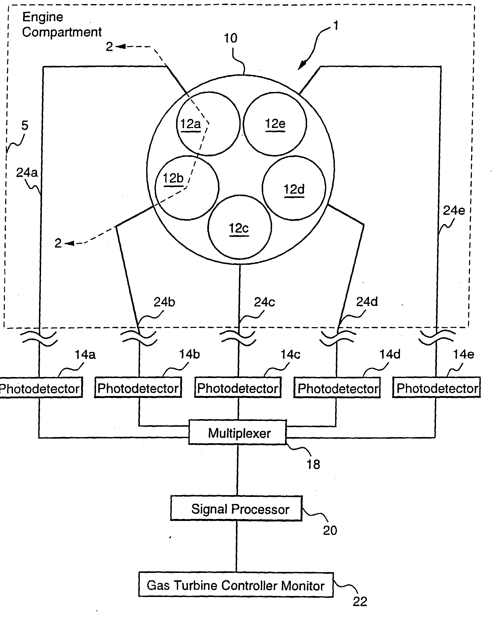
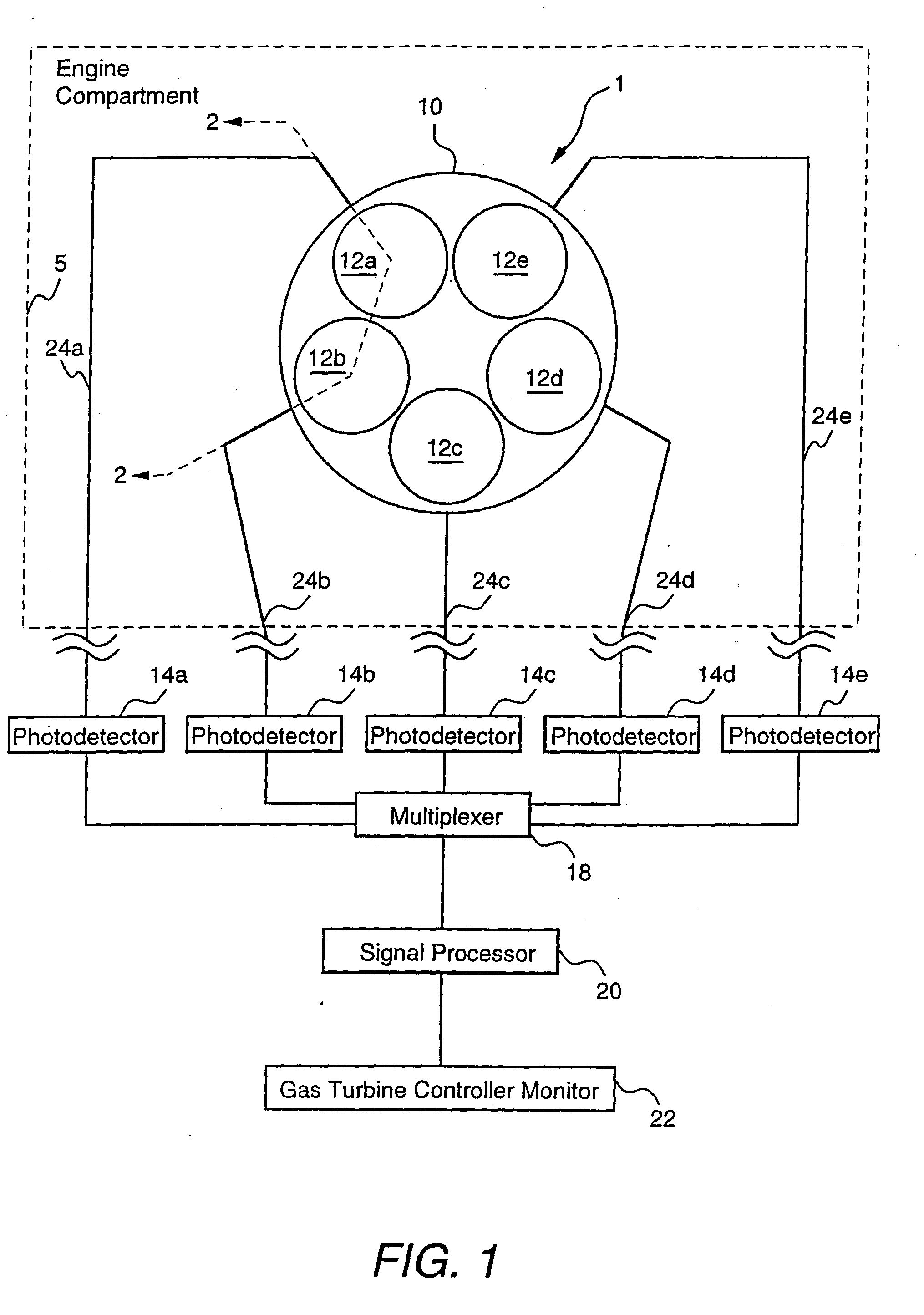
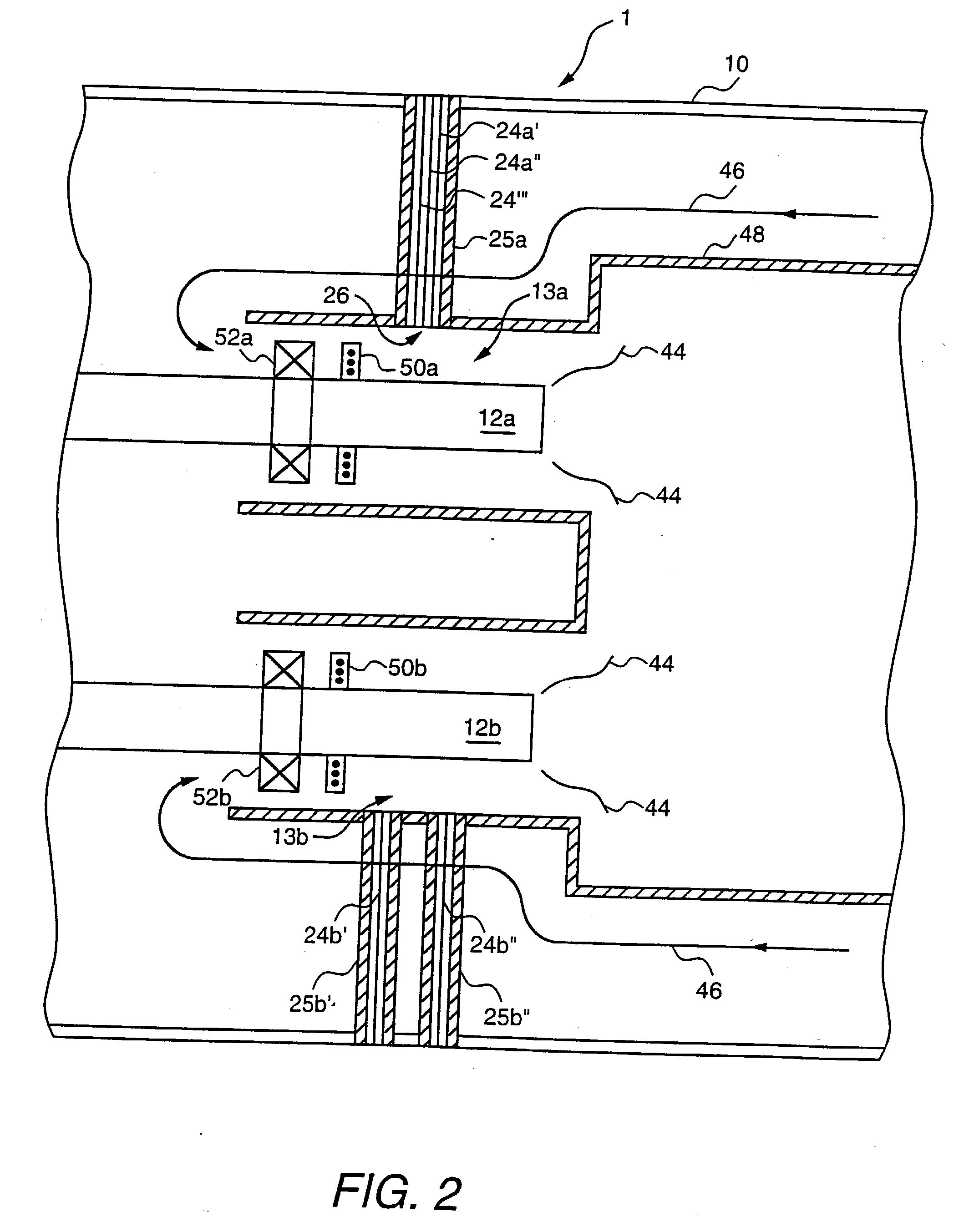
[0025]FIG. 1 is a block diagram of a flashback protection embodiment of the present invention, and FIG. 2 is a sectional view of a portion of the embodiment of FIG. 1.
[0026] A combustor 1 includes at least one fuel nozzle (and preferably a plurality of fuel nozzles 12a, 12b, 12c, 12d, and 12e) capable of supplying flames 44. Each of the fuel nozzles is monitored using a fiber optic element 24a, 24b, 24c, 24d, or 24e comprising at least one respective optical fiber which sends an optical signal to a respective photodetector 14a, 14b, 14c, 14d, or 14e.
[0027] If desired, each optical fiber optic element 24a, 24b, 24c, 24d, or 24e may comprise several optical fibers in a bundle as shown by optical fibers 24a′, 24a″, and 24a′″ in FIG. 2.
[0028] In one embodiment each fiber optic element includes at least one optical multi-mode fiber pressure-sealed at one end 26 or both ends into a protective tube (shown as tube 25a in FIG. 2) which is capable of withstanding the operating environment....
PUM
 Abstract
Description
Claims
Application Information
 - R&D
- Intellectual Property
- Life Sciences
- Materials
- Tech Scout
- Unparalleled Data Quality
- Higher Quality Content
- 60% Fewer Hallucinations
Browse by: Latest US Patents, China's latest patents, Technical Efficacy Thesaurus, Application Domain, Technology Topic, Popular Technical Reports.
© 2025 PatSnap. All rights reserved.Legal|Privacy policy|Modern Slavery Act Transparency Statement|Sitemap|About US| Contact US: help@patsnap.com


